Camera with rotation function

A technology of rotating function and camera, applied in the field of computer peripheral hardware equipment, can solve problems such as the contradiction of camera adjustment direction

Inactive Publication Date: 2015-06-10
XIAN KUNPENG INFORMATION TECH
View PDF0 Cites 8 Cited by
  • Summary
  • Abstract
  • Description
  • Claims
  • Application Information

AI Technical Summary

Problems solved by technology

[0003] The purpose of the invention is to overcome the problem that the existing camera head is fixed in the direction of adjustment and there is a contradiction

Method used


Image

  • Camera with rotation function

Examples


Embodiment 1

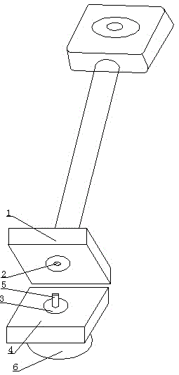
[0012] above as figure 1 A camera with a rotation function shown includes a support rod base 1, a base 4, and a threaded groove 2 arranged on the bottom surface of the support rod base 1, and a bearing 3 is fixedly connected to the top surface of the base 4. Including a connecting rod 5, one end of the connecting rod 5 is fixedly connected with the bearing 3, and the other end of the connecting rod 5 is provided with a thread, which cooperates with the threaded groove 2 to fix the support rod base 1; the camera with a rotating function can be used Fix the camera at the required place to prevent the camera from being broken due to carelessness, and the orientation of the camera can be adjusted, which is very convenient.

Embodiment 2

[0014] Above-mentioned threaded groove 2 is arranged on the center of the bottom surface of support bar base 1, and bearing 3 is arranged on the center of the top surface of base 4; Cooperate with the connecting rod 5 to adjust the direction of the mini camera.


PUM


Abstract

The invention belongs to the technical field of computer peripheral hardware equipment and particularly relates to a camera with a rotation function. The camera with the rotation function comprises a support rod base, a base, a thread groove and a connecting rod, wherein the thread groove is arranged in the bottom surface of the support rod base, the top surface of the base is fixedly connected to a bearing, one end of the connecting rod is fixedly connected to the bearing, and a screw thread is arranged on the other end of the connecting rod and is matched with the thread groove so as to fix the support rod base. According to the camera with the rotation function, the camera can be fixed at a required place in use so as to prevent the camera from being broken due to careless operation, and furthermore, the orientation of the camera can be adjusted, so that the camera is very convenient.

Description

technical field [0001] The invention belongs to the technical field of computer peripheral hardware equipment, and in particular relates to a camera with a rotation function. Background technique [0002] Camera (CAMERA), also known as computer camera, computer eye, etc., is a video input device that is widely used in video conferencing, telemedicine and real-time monitoring. Ordinary people can also talk and communicate with each other through the network with images and sounds through the camera. In addition, people can also use it for various current popular digital images and audio-visual processing; however, the existing cameras are easy to cause accidental damage during use due to their small size, and there is a contradiction fixed in the direction of adjustment. Contents of the invention [0003] The purpose of the present invention is to overcome the problem that the existing camera head is fixed in the direction of adjustment, which is contradictory. [0004] F...

Claims


Application Information

Patent Timeline
Patent Type & Authority Applications(China)
IPC IPC(8): H04N5/225F16M11/06F16M11/18
Inventor 焦素梅
Owner XIAN KUNPENG INFORMATION TECH
Why Eureka
Try Eureka