Field calibration ground hydraulic tester

A hydraulic tester and on-site calibration technology, which is applied in the fields of ground equipment, fluid pressure actuation system testing, aircraft component testing, etc., can solve the problem that the hydraulic system cannot realize the traceability of the value

Inactive Publication Date: 2015-06-17
HARBIN
View PDF8 Cites 1 Cited by
  • Summary
  • Abstract
  • Description
  • Claims
  • Application Information

AI Technical Summary

Problems solved by technology

[0002] Under traditional circumstances, the hydraulic system of the aircraft cannot realize the traceability of the value when it is onboard. In order to realize the traceability of the value

Method used


Image

  • Field calibration ground hydraulic tester

Examples


Embodiment Construction

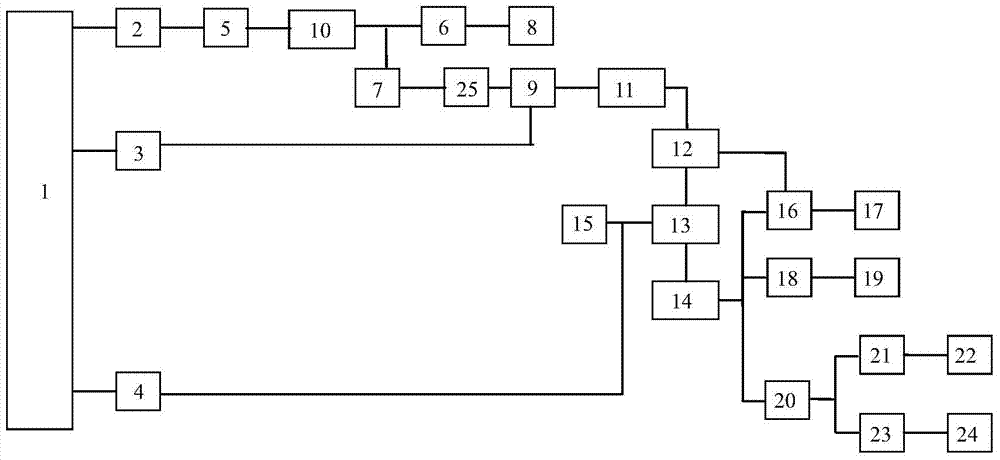
[0011] The ground hydraulic tester is mainly composed of a displacement adjustment module 11, a main pump oil suction group 3, an auxiliary pump oil suction group 4, a high pressure filter 12, an air cooler 7 and the like.

[0012] see figure 1 , the on-site calibration ground hydraulic tester includes a displacement adjustment module 11, a main pump oil suction group 3, an auxiliary pump oil suction group 4, a high-pressure filter 12, and an air cooler 7. It is characterized in that: the oil tank drain switch 1 is connected to the vacuum Switch 2, main pump oil suction group 3, auxiliary pump oil suction group 4 are connected; vacuum switch 2 is connected with pressure filter 5 and differential pressure switch 10, pressure filter 5 is connected with pressure switch 6 and air cooler 7 respectively, pressure switch 6 is connected with The auxiliary pump outlet pressure 8 is connected; the air cooler 7 is connected with the temperature sensor 25, the temperature sensor 25 is con...


PUM


Abstract

The invention belongs to a ground hydraulic tester used for detecting liquid oil of a helicopter. The ground hydraulic tester comprises a displacement adjusting module (11), a main oil pumping set (3), an auxiliary oil pumping set (4), a high-pressure filter (12), and an air cooler (7). The hydraulic tester is mainly used for realizing detection of pressure and flow of liquid oil on the helicopter. Under a traditional condition, a hydraulic system of the helicopter cannot realize traceability of value onboard, and in order to realize traceability of value, the ground hydraulic tester is designed. The ground hydraulic tester is mainly used for realizing detection of pressure and flow of the liquid oil on the helicopter and realizing traceability of value.

Description

technical field [0001] The utility invention belongs to the field of helicopter ground hydraulic systems, and in particular relates to pressure and flow value traceability equipment in the hydraulic system. Background technique [0002] In the traditional situation, the hydraulic system of the aircraft cannot realize the traceability of the value when it is onboard. In order to realize the traceability of the value. Contents of the invention [0003] The technical problem to be solved in the present invention: [0004] Traditionally, the hydraulic system of an aircraft cannot be traced to its source when it is onboard. [0005] Technical scheme of the present invention: [0006] The on-site calibration ground hydraulic tester includes a displacement adjustment module 11, a main pump oil suction group 3, an auxiliary pump oil suction group 4, a high pressure filter 12, an air cooler 7, and a fuel tank drain switch 1 respectively connected to the vacuum switch 2 and the ma...

Claims


Application Information

Patent Timeline
Patent Type & Authority Applications(China)
IPC IPC(8): F15B19/00B64F5/00B64F5/60
CPCB64F5/00F15B19/00F15B21/041
Inventor 张蕊
Owner HARBIN
Why Eureka
Try Eureka