
Systems and methods for measuring brightness response of a camera operating in automatic exposure mode

A luminance response and luminance technology, applied in TV, electrical components, image communication, etc., can solve problems such as hindering response curve measurement

Inactive Publication Date: 2015-06-17
ANRITSU CORP
View PDF5 Cites 3 Cited by
  • Summary
  • Abstract
  • Description
  • Claims
  • Application Information

AI Technical Summary

Problems solved by technology

[0004] Unfortunately, automatic exposure control prevents the measurement of response curves that are produced when testing cameras included in UE devices

Method used


Image

  • Systems and methods for measuring brightness response of a camera operating in automatic exposure mode
  • Systems and methods for measuring brightness response of a camera operating in automatic exposure mode
  • Systems and methods for measuring brightness response of a camera operating in automatic exposure mode

Examples


Embodiment Construction

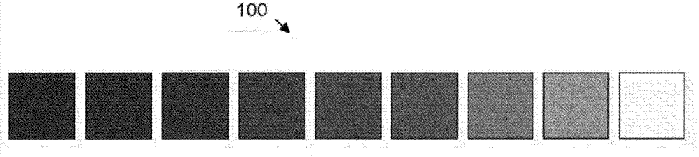
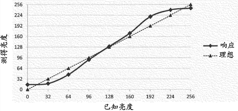
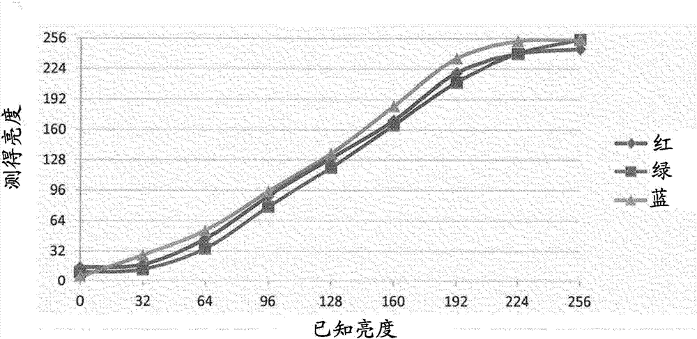
[0025] The following description presents the best mode presently contemplated for practicing various embodiments of the invention. This description should not be taken as limiting, but merely for the purpose of illustrating the general principles of the invention. The scope of the invention should be determined with reference to the claims. In the ensuing description of the invention, like numerals or reference designators will be used to refer to like parts or elements throughout. in addition, Figure 1 to Figure 9 The first digit of the reference designation introduced in and Figure 10 to Figure 13 The first two digits of a reference number introduced in identify the figure in which the reference number first appears.

[0026] It should be apparent to those skilled in the art that the invention as described below can be implemented in many different embodiments in hardware, software, firmware and / or entities shown in the figures. In addition, frame rates and brightness...


PUM


Abstract

A method to measure a brightness response of a camera comprises obtaining a plurality of brightness measurements and determining for one or more of the plurality of brightness measurements a captured brightness of the captured image. Obtaining each of the plurality of brightness measurements includes presenting to the camera at least one test sample having known brightness, capturing via the camera an image of the at least one test sample, and presenting to the camera at least one compensation sample having compensating brightness selected based on the known brightness of the at least one test sample. The at least one test sample and the at least one compensation sample are selectable and presentable in combination such that an average exposure interpreted by the camera is substantially the same for each of the plurality of brightness measurements.

Description

technical field [0001] The present invention relates to measuring camera response to changes in lighting conditions. Background technique [0002] It is a regular task of telecommunications network operators to evaluate the performance of user equipment (UE) devices, especially in newly introduced telecommunications applications for operation on the operator's network. Typically, the UE device is assembled by the operator's manufacturer partner and sent for evaluation. Different specifications must be met for different subcomponents of the UE device. For example, the displays and cameras of UE devices such as cell phones and tablets must operate under a wide range of lighting conditions. For cameras, various tests are performed, including measuring the camera's response to different brightness levels under lighting conditions. [0003] Most cameras of UE devices include automatic exposure control features. Automatic exposure control is convenient for the end user because...

Claims


Application Information

Patent Timeline
Patent Type & Authority Applications(China)
IPC IPC(8): H04N17/00H04N17/02
CPCH04N17/02
Inventor J·P·德伦布什
Owner ANRITSU CORP
Features
  • Generate Ideas
  • Intellectual Property
  • Life Sciences
  • Materials
  • Tech Scout
  • Unparalleled Data Quality
  • Higher Quality Content
  • 60% Fewer Hallucinations
Learn More