
Underfill detection system for a test sensor

a detection system and sensor technology, applied in the field of electrochemical biosensing, can solve problems such as affecting the judgment of people, affecting the accuracy of the test,

Inactive Publication Date: 2005-11-01
ASCENSIA DIABETES CARE HLDG AG
View PDF11 Cites 119 Cited by
  • Summary
  • Abstract
  • Description
  • Claims
  • Application Information

AI Technical Summary

Benefits of technology

The present invention is a test sensor that can measure the concentration of a substance in a liquid sample. It has two electrodes and a reagent that helps with the measurement. The sensor has a capillary channel to collect the sample and a conductor outside the channel. When the sample reaches the conductor, it signals that the channel is full. The technical effect of this invention is to provide a simple and efficient way to measure substances in liquids.

Problems solved by technology

The failure to take corrective action can have serious implications.
When blood glucose levels drop too low—a condition known as hypoglycemia—a person can become nervous, shaky, and confused.
That person's judgment may become impaired and that person may eventually pass out.
Both conditions, hypoglycemia and hyperglycemia, are potentially life-threatening emergencies.
One problem associated with some lancing and / or testing devices is that the requisite amount of blood for accurate test results is not always obtained.
Roughly thirty percent of lances do not produce enough blood for analysis.
If less than this amount is obtained, the test results may be erroneous and a test sensor is wasted.
More serious an issue, however, is that the user may be relying on inaccurate results when an insufficient sample volume is harvested.
Another problem associated with conventional lancing devices is that there is no mechanism to let the user know whether the correct amount of blood has been obtained for accurate analysis.
However, this visual comparison is subjective and often produces inconsistent results.
However, this adds time to the overall testing process and also results in an increased amount of wasted blood.
Often, requiring an increased amount of blood translates into a more “invasive” procedure meaning that the obtaining of the same can take more time and be more painful.

Method used


Image

  • Underfill detection system for a test sensor
  • Underfill detection system for a test sensor
  • Underfill detection system for a test sensor

Examples


Embodiment Construction

[0015]As discussed in the background section, test sensors are commonly used to measure the amount of glucose in a person's blood. One type of sensor for use in the determination of a person's blood glucose level is an electrochemical sensor. Such a sensor is described in commonly owned U.S. Pat. No. 5,759,364, which is incorporated herein by reference in its entirety. Other types of sensing include calorimetric sensing, which is described in commonly owned U.S. Pat. No. 5,723,284, which is incorporated herein by reference in its entirety.

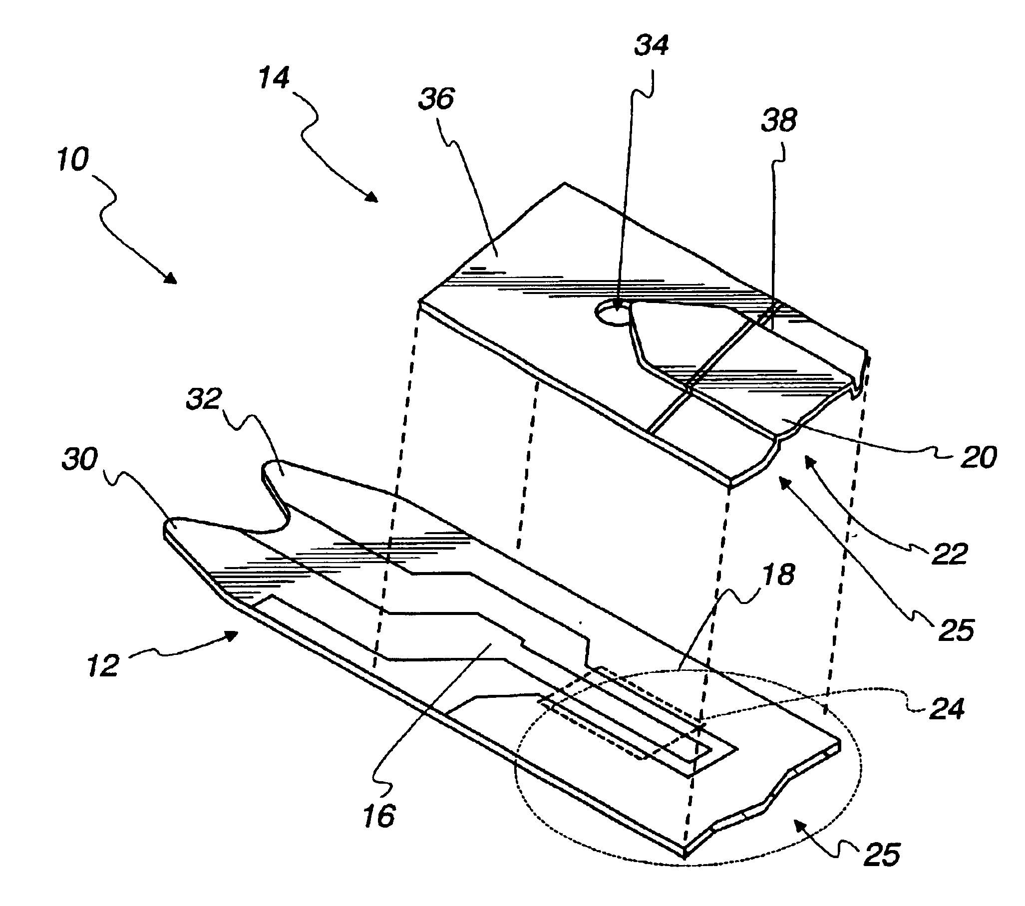
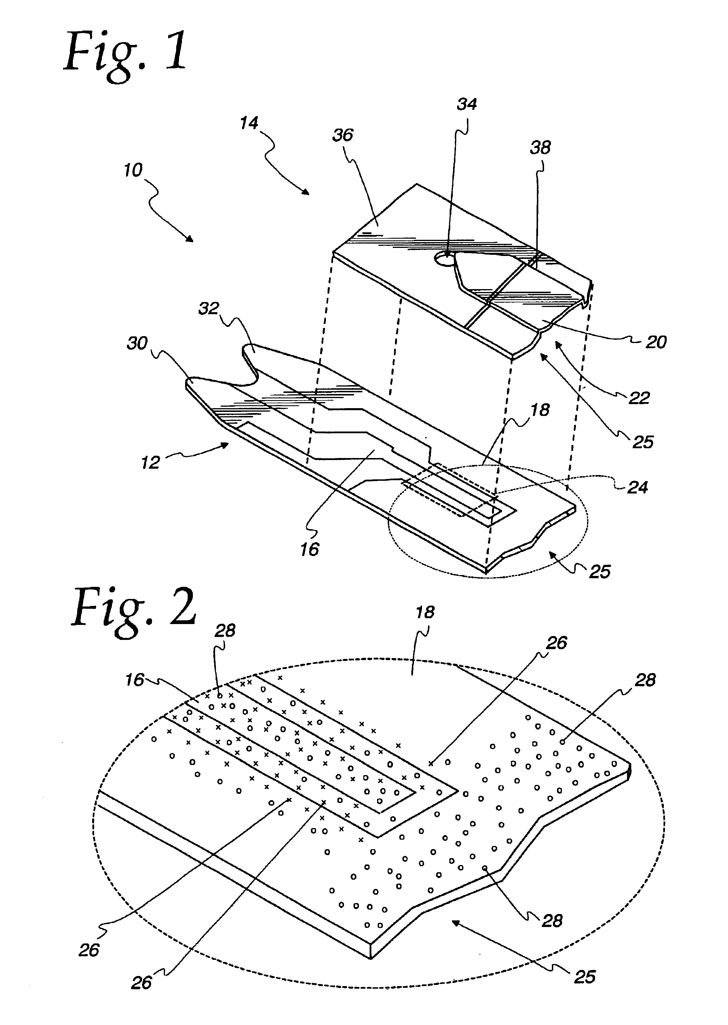
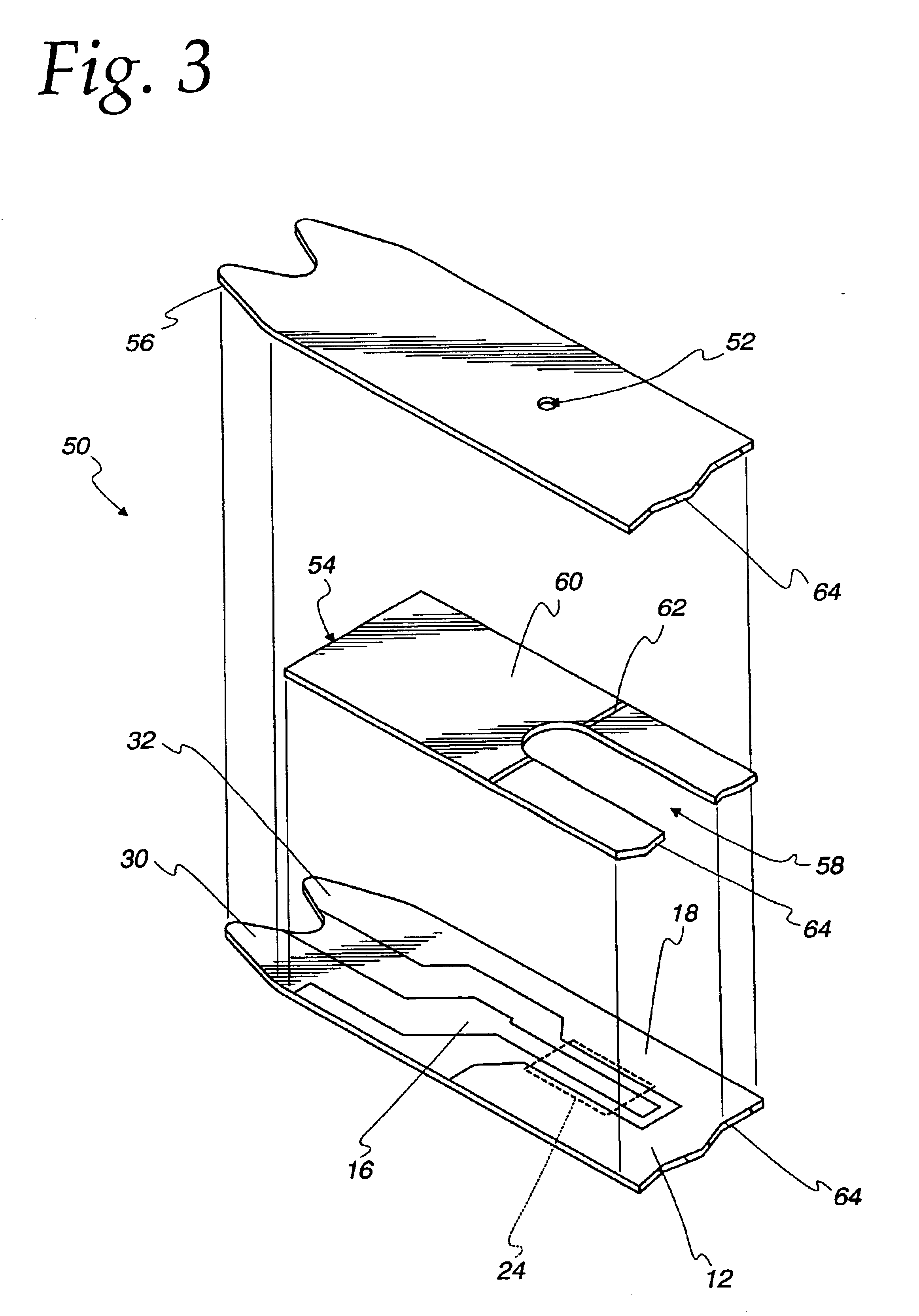
[0016]Referring now to FIG. 1, there is shown a test sensor 10 according to one embodiment of the present invention. The test sensor 10 includes a base plate 12 and a lid 14. The base plate 12 includes a working electrode 16 and a counter-reference electrode 18 printed on the surface of the base plate 12. The lid 14 includes a raised portion 20, the underside of which forms three side of a capillary channel 22. The base plate 12 forms the fourth si...


PUM

PropertyMeasurementUnit
thicknessaaaaaaaaaa
diameteraaaaaaaaaa
diameteraaaaaaaaaa

Abstract

A test sensor having a pair of electrodes and a reagent for electrochemically measuring the concentration of the analyte in a liquid sample. The test sensor comprises a capillary channel for collecting the liquid sample and a conductor disposed outside the capillary channel. The conductor is in fluid communication with the capillary channel. The liquid test sample is collected and moved through the capillary channel. The liquid test sample contacts the conductor when the capillary channel is substantially full to signal a full condition.

Description

[0001]This application claims the benefit of U.S. Provisional Application No. 60 / 296,910, filed Jun. 11, 2001.FIELD OF THE INVENTION[0002]The present invention relates generally to electrochemical biosensing for quantifying a specific component (analyte) in a liquid sample, and more particularly, to an underfill detection system for use with an electrochemical biosensor.BACKGROUND OF THE INVENTION[0003]It is often necessary to quickly obtain a sample of blood and perform an analysis of the blood sample. One example of a need for obtaining a sample of blood is in connection with a blood glucose monitoring system, which a user must frequently use to monitor the user's blood glucose level.[0004]Those who have irregular blood glucose concentration levels are medically required to regularly self-monitor their blood glucose concentration level. An irregular blood glucose level can be brought on by a variety of reasons including illness such as diabetes. The purpose of monitoring the blood...

Claims


Application Information

Patent Timeline
Patent Type & Authority Patents(United States)
IPC IPC(8): C12Q1/00G01N27/30G01N33/487G01N33/483G01N27/28G01N27/327G01N27/416G01N33/66
CPCC12Q1/006G01N27/3272G01N27/308
Inventor CHARLTON, STEVEN C.
Owner ASCENSIA DIABETES CARE HLDG AG
Learn More