Optical power meter with static electricity tester

A technology of optical power meter and tester, which is applied in the direction of electrostatic field measurement, instrument, measuring device, etc. It can solve the problem that the optical power meter has no surrounding environment or static detection of objects, and achieves the effect of convenient installation and disassembly and good stability

Inactive Publication Date: 2015-06-24
XIAN MEIYU INFORMATION TECH
View PDF0 Cites 0 Cited by
  • Summary
  • Abstract
  • Description
  • Claims
  • Application Information

AI Technical Summary

Problems solved by technology

[0003] The purpose of the present invention is to overcome the problem that the optical power meter does not detect the static electricity of the surrounding environment or objects in the prior art

Method used


Image

  • Optical power meter with static electricity tester

Examples


Embodiment 1

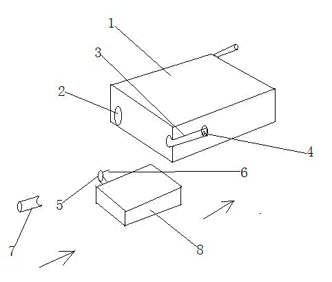
[0010] Embodiment one: combined with attached figure 1 describe.

[0011] An optical power meter with an electrostatic tester, comprising an optical power meter body 1 and a power supply 2 thereof, the side of the body 1 is formed with a spherical blind port chute 3; the spherical blind port chute 3 has a blind end There is an electrical interface 4 connected to the power supply 2; the spherical blind port chute 3 has a built-in electrostatic tester 8 with a ball head 5; the ball head 5 has a plug 6 adapted to the electrical interface 4.

[0012] This scheme realizes the problem that the optical power meter has the function of detecting the surrounding environment or static parameters of objects, and is convenient to install and disassemble.

Embodiment 2

[0013] Embodiment two, combined with figure 1 describe.

[0014] On the basis of the first embodiment, the spherical blind groove 3 is built with a rubber cylindrical block 7; the rubber cylindrical block 7 is made into a semicircular arc shape.

[0015] The preferred rubber column block of this scheme can make it more stable after insertion.


PUM


Abstract

The invention belongs to the technical field of electronic products and provides an optical power meter with a static electricity tester. The optical power meter with the static electricity tester comprises an optical power meter body and a power supply thereof, and a spherical blind opening sliding groove is formed in the side face of the body. An electric interface connected with the power supply is formed in the blind opening end of the spherical blind opening sliding groove. The static electricity tester with a ball head is arranged in the spherical blind opening sliding groove. The ball head is provided with a plug matched with the electric interface. A rubber pillar block is arranged in the spherical blind opening sliding groove. The rubber pillar block is in a semi-arc shape. According to the scheme, the optical power meter has the function of detecting the static electricity parameters of ambience or ambient objects, and is convenient to assemble and disassemble. The preferred rubber pillar block can enable the optical power meter to be better in stability after insertion.

Description

technical field [0001] The invention belongs to the technical field of electronic products, and in particular relates to an optical power meter with an electrostatic tester. Background technique [0002] Most of the existing optical power meters have made relevant innovative designs in terms of their practicability. However, in actual use, there are different requirements due to different occasions, such as the problem of detecting the surrounding environment or static electricity of objects; however, the existing optical power There is no design in this aspect of the meter, so its scope of use is limited to a certain extent, which is a problem worth pondering. Contents of the invention [0003] The purpose of the present invention is to overcome the problem that the optical power meter in the prior art does not detect the static electricity of the surrounding environment or objects. [0004] For this reason, the present invention provides a kind of optical power mete...

Claims


Application Information

Patent Timeline
Patent Type & Authority Applications(China)
IPC IPC(8): G01R29/12G01J1/02
Inventor 赵腾
Owner XIAN MEIYU INFORMATION TECH
Why Eureka
Try Eureka