Switching assembly

A technology of switch components and connecting rods, which is applied in the mechanical field, can solve the problems that cannot be applied to power transmission systems, high-voltage applications, and applications that cannot apply to large opening distances, and achieve the effect of increasing the opening distance

Active Publication Date: 2015-06-24
NR ELECTRIC CO LTD +1
View PDF7 Cites 0 Cited by
  • Summary
  • Abstract
  • Description
  • Claims
  • Application Information

AI Technical Summary

Problems solved by technology

[0003] At present, the fast switch based on the electromagnetic repulsion operating mechanism is usually used, but the electromagnetic repulsion mechanism is only suitable for the application of small opening distance and low voltage, and cannot be applied to the application of large opening distance, so the fast switch based on the electromagnetic repulsion operating mechanism cannot be applied in Medium and high voltage applications in power transmission systems

Method used


Image

  • Switching assembly
  • Switching assembly
  • Switching assembly

Examples


Embodiment Construction

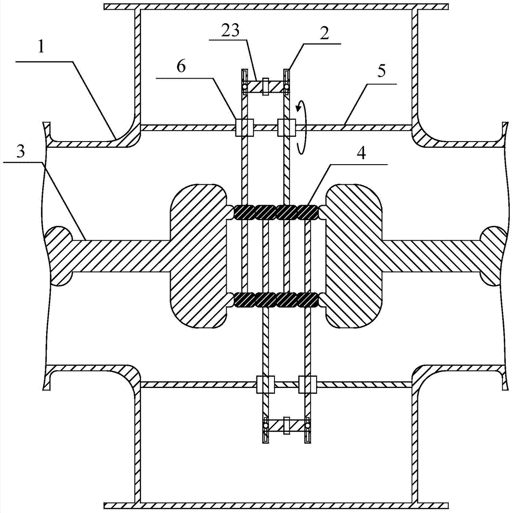
[0029] In practical applications, it is possible to perform figure 1 settings shown. figure 1 Among them, the switch assembly of the present invention mainly includes a rotating link 2 and a rotating structure 6 ; wherein, the rotating link 2 is provided with a conductive block 4 , and the rotating link 2 is connected to the bracket 5 in the container 1 through the rotating structure 6 .

[0030] The conductive block 4 can be arranged at one end of the rotating link 2 .

[0031] Due to the existence of the rotating structure 6 , the rotating link 2 can rotate in the direction shown in the figure (or the opposite direction) on the support 5 . The above components together with the static contact 3 arranged in the container 1 form a relatively complete switch as a whole.

[0032] When the rotating connecting rod 2 rotates to a specific posture, the conductive block 4 on the rotating connecting rod 2 contacts the static contact 3 in the container 1; when the rotating connecting...


PUM


Abstract

The invention discloses a switching assembly. The switching assembly is characterized by comprising rotary connecting rods and rotary structures for making the rotary connecting rods rotate. The rotary connecting rods are provided with conducting blocks for forming a conducting path.

Description

technical field [0001] The invention relates to the mechanical field, in particular to a switch assembly. Background technique [0002] For medium and high voltage applications in power transmission systems, switches that open and close quickly are required. While the opening and closing speed is required, it is also required that the switch has a large enough opening distance when it is separated to ensure the insulation performance. [0003] At present, the fast switch based on the electromagnetic repulsion operating mechanism is usually used, but the electromagnetic repulsion mechanism is only suitable for the application of small opening distance and low voltage, and cannot be applied to the application of large opening distance, so the fast switch based on the electromagnetic repulsion operating mechanism cannot be applied in Medium and high voltage applications in power transmission systems. Contents of the invention [0004] In view of this, the present invention ...

Claims


Application Information

Patent Timeline
Patent Type & Authority Applications(China)
IPC IPC(8): H01H3/32
CPCH01H3/32
Inventor 吕玮刘彬黄德祥杨浩石亲民王宇杨兵方太勋石巍
Owner NR ELECTRIC CO LTD
Why Eureka
Try Eureka