A waterproof button structure and electronic equipment
A technology of buttons and conductive coils, which is applied in the field of waterproof button structure design, and can solve problems such as non-waterproof
- Summary
- Abstract
- Description
- Claims
- Application Information
AI Technical Summary
Problems solved by technology
Method used
Image

Examples
Embodiment 1
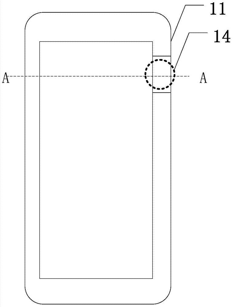
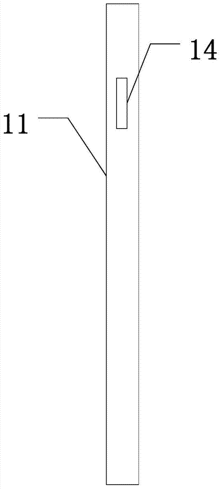
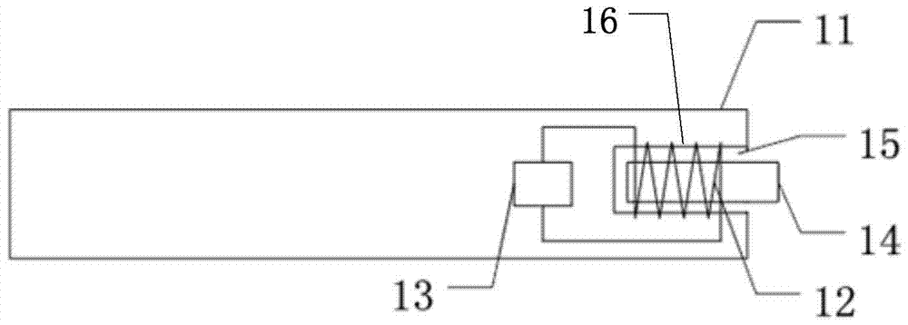
[0030] An embodiment of the present invention provides a waterproof button structure, figure 1 It is a top view of a waterproof button structure provided by Embodiment 1 of the present invention, figure 2 It is a side view of a waterproof button structure provided by Embodiment 1 of the present invention, image 3 for along figure 1 Sectional view in direction AA. see figure 1 and figure 2 , the waterproof key structure includes: a closed casing 11 and a dial 14 . see image 3 , the closed casing 11 is provided with a groove 15; the waterproof button structure also includes a conductive coil 12, the conductive coil 12 is located inside the closed casing 11 and is wound around the groove 15; the sensor 13. The inductor 13 is located in the closed casing 11 and is electrically connected to both ends of the conductive coil 12; the dial 14 is magnetic and is arranged outside the closed casing 11 and is located in the closed casing 11. In the groove 14 ; when the dial 14 m...
Embodiment 2
[0037] The embodiment of the present invention is a further optimization of the first embodiment above, Figure 5 It is a top view of a waterproof button structure provided by Embodiment 2 of the present invention, Image 6 It is a side view of a waterproof button structure provided by Embodiment 2 of the present invention, Figure 7 for along Figure 5 Sectional view in direction AA. see Figure 5 and Image 6 , the waterproof button structure includes: a closed casing 21 and a dial 24 . see Figure 7 , the closed casing 21 is provided with a groove 25; the waterproof button structure also includes a conductive coil 22, the conductive coil 22 is located inside the closed casing 21 and wound around the groove 25; the inductor 23, The inductor 23 is located in the closed casing 21 and is electrically connected to both ends of the conductive coil 22; the dial 24 is magnetic and is arranged outside the closed casing 21 and located in the groove 25 ; when the dial 24 moves ...
Embodiment 3
[0042] The embodiment of the present invention also provides an electronic device, Figure 9 A schematic structural diagram of an electronic device provided in Embodiment 3 of the present invention, such as Figure 9 As shown, the electronic device includes a waterproof key structure 31, and may also include a drive circuit and other devices for supporting the normal operation of the electronic device. Wherein, the waterproof key structure 31 is the waterproof key structure described in each of the above embodiments, and the electronic device may be one of a mobile phone, a tablet computer, an electronic paper, an electronic photo frame, and the like. It should be noted, Figure 9 It is only a structural example of an electronic device provided by the embodiment of the present invention, and the embodiment of the present invention is not limited to Figure 9 The shown appearance and structural configuration only need to include the waterproof key structure provided by the ab...
PUM
 Abstract
Description
Claims
Application Information
 - R&D
- Intellectual Property
- Life Sciences
- Materials
- Tech Scout
- Unparalleled Data Quality
- Higher Quality Content
- 60% Fewer Hallucinations
Browse by: Latest US Patents, China's latest patents, Technical Efficacy Thesaurus, Application Domain, Technology Topic, Popular Technical Reports.
© 2025 PatSnap. All rights reserved.Legal|Privacy policy|Modern Slavery Act Transparency Statement|Sitemap|About US| Contact US: help@patsnap.com