Optical switching framework

An optical switching architecture and optical signal technology, applied in the field of optical switching architecture, can solve the problem that the optical switching architecture does not satisfy wavelength independence and direction independence, etc.

Active Publication Date: 2015-06-24
TONGDING INTERCONNECTION INFORMATION CO LTD
View PDF3 Cites 11 Cited by
  • Summary
  • Abstract
  • Description
  • Claims
  • Application Information

AI Technical Summary

Problems solved by technology

[0008] In order to solve the problem that the existing optical switching architecture does not satisfy the wavelength in

Method used


Image

  • Optical switching framework
  • Optical switching framework
  • Optical switching framework

Examples


Embodiment Construction

[0108] In order to make the object, technical solution and advantages of the present invention clearer, the embodiments of the present invention will be further described in detail below in conjunction with the accompanying drawings.

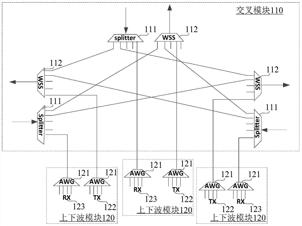
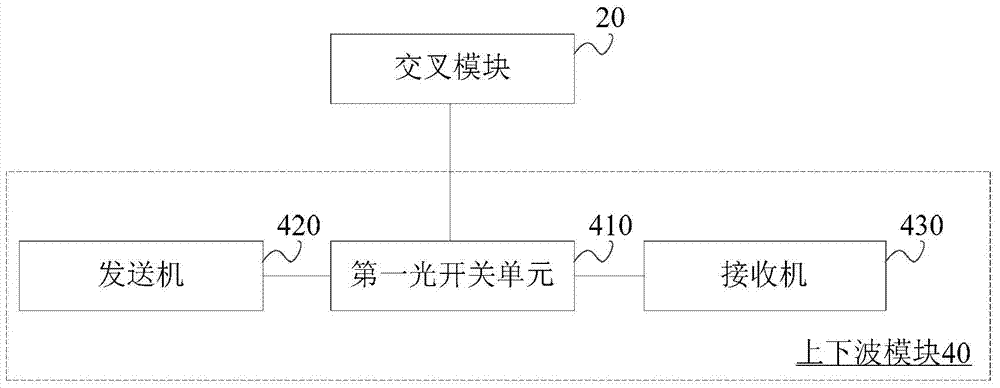
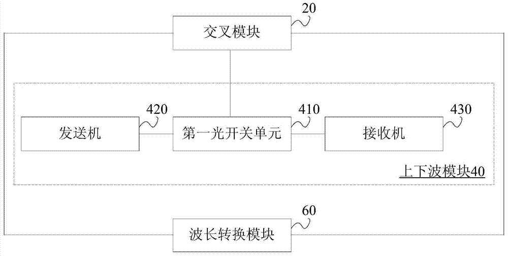
[0109] refer to figure 2 , which shows a schematic structural diagram of an optical switching architecture provided by an embodiment of the present invention. The optical switching architecture includes: a cross-connect module 20 and an add / drop module 40 connected to the cross-connect module 20 .

[0110] The intersection module 20 includes n sets of input terminals and output terminals belonging to different dimensions, n≥2.

[0111] Add / drop module 40, including a first optical switch unit 410 connected to the input end and output end, at least one transmitter 420 connected to the first optical switch unit 410, and at least one receiver 430 connected to the first optical switch unit 410 .

[0112] The first optical switch unit 410 is conf...


PUM


Abstract

The present invention relates to the field of communications. Disclosed is an optical switching architecture comprising cross-connect modules and add/drop modules connected to the cross-connect modules; the cross-connect modules comprise n groups of input ends and output ends of different dimensions; and the add/drop modules comprise first optical switch units connected to the input ends and the output ends, with transmitters and receivers connected to the first optical switch units. The present invention adds first optical switch units to an optical switching architecture, thus solving the problem that the optical switching architecture provided in the related art fails colorless and directionless requirements, and providing more flexible wavelength scheduling.

Description

technical field [0001] The invention relates to the communication field, in particular to an optical switching architecture. Background technique [0002] The optical switching architecture is used to exchange optical signals between different dimensions. It is the core module in the optical network switching system, and its performance determines the service capability of the entire optical network switching system. [0003] Due to the maturity of optical wavelength division multiplexing technology, the rapid growth of transmission capacity has brought pressure and power to the development of optical network switching systems. The scale of optical network switching systems in communication networks is getting larger and higher, and the operating speed is getting higher and higher. From the perspective of the development trend of the entire optical network switching technology, the future optical switching architecture needs to implement the switching characteristics of CDC....

Claims


Application Information

Patent Timeline
IPC IPC(8): H04J14/02H04L12/933
CPCH04Q11/0005H04Q2011/0018H04Q2011/005
Inventor 蒋臣迪耿东玉赵星
Owner TONGDING INTERCONNECTION INFORMATION CO LTD
Why Eureka
Try Eureka