
A visual inspection method and device for root cleaning of crankshaft shoulder

A visual inspection and shaft shoulder technology, applied in measuring devices, optical devices, instruments, etc., can solve the problems of high inspection cost, low inspection accuracy, long inspection time, etc., achieve efficient identification and inspection, enhance anti-interference, The effect of reducing inspection costs

Inactive Publication Date: 2017-04-05
NORTH CHINA UNIVERSITY OF TECHNOLOGY
View PDF7 Cites 1 Cited by
  • Summary
  • Abstract
  • Description
  • Claims
  • Application Information

AI Technical Summary

Problems solved by technology

[0005] In order to overcome the deficiencies of the prior art, the present invention provides a visual inspection method and device for cleaning the root of the crankshaft shoulder, which solves the problems of low detection accuracy, long detection time and high detection cost in the prior art.

Method used

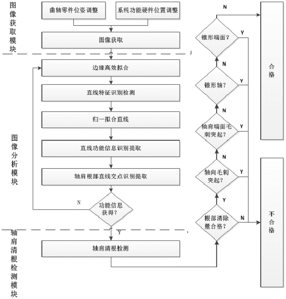
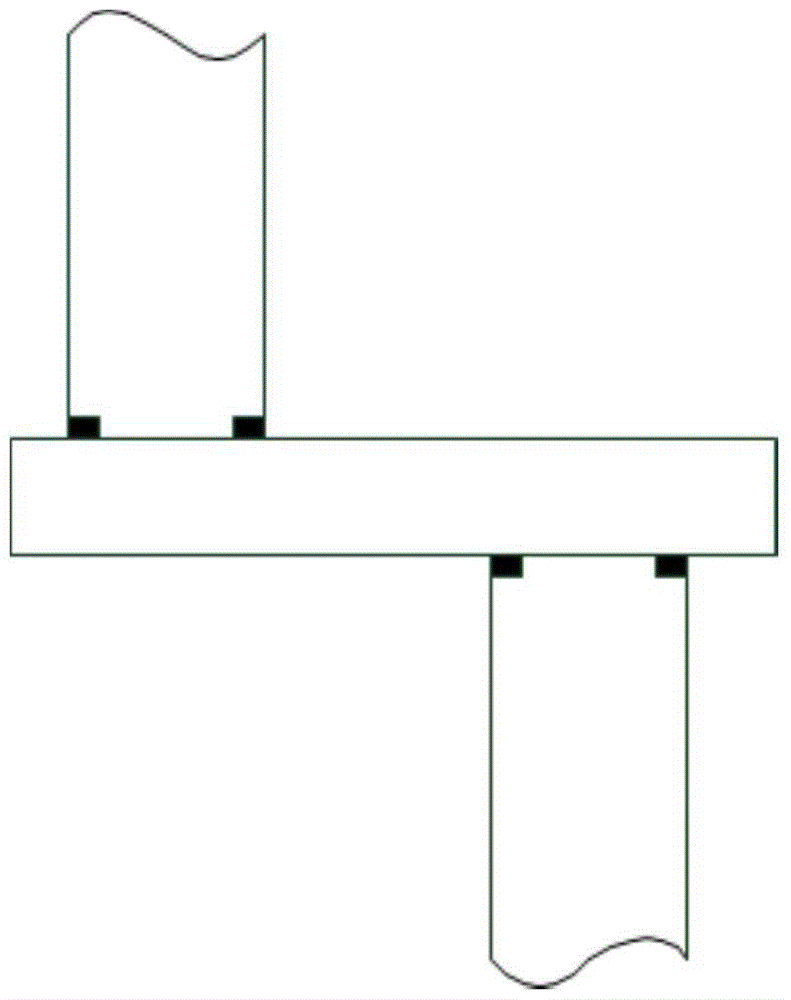
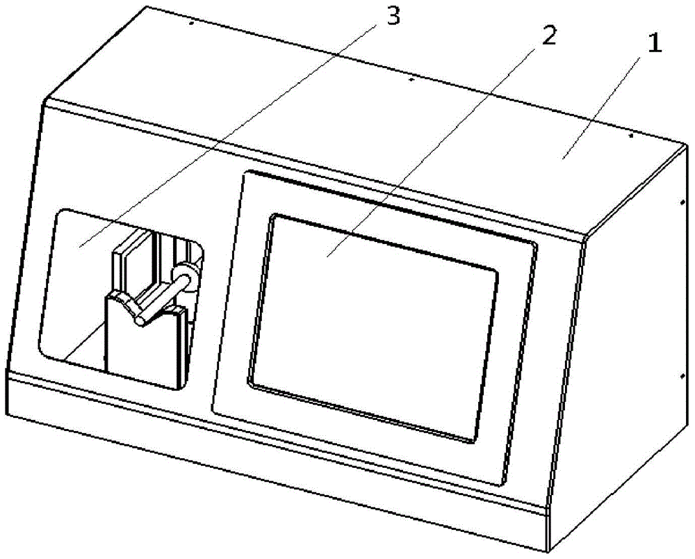

Image

  • A visual inspection method and device for root cleaning of crankshaft shoulder
  • A visual inspection method and device for root cleaning of crankshaft shoulder
  • A visual inspection method and device for root cleaning of crankshaft shoulder

Examples


Embodiment Construction

[0042] Preferred embodiments of the present invention will be described in detail below in conjunction with the accompanying drawings.

[0043]For crankshaft parts on the engine, its positioning shoulder needs to be close to the end face of the bearing to meet the product requirements. Such a crankshaft has powerful functions and requires high processing parameters, and is a key part of the engine. After the rough machining process is completed, the crankshaft is generally ground and cleaned with a special grinding wheel. It mainly has the following two functions: firstly remove the processing redundancy such as root protrusions and burrs, and further remove a certain amount of material at the root to ensure the close fit between the shaft shoulder end face and the bearing end face. The second is the finishing of the curved surface of the crankshaft to meet the matching requirements with the inner ring of the bearing.

[0044] Through industrial field research, it was conclu...


PUM


Abstract

The invention provides a root removal visual inspection method for shaft shoulders of crankshafts. The root removal visual inspection method sequentially includes steps of [1], acquiring images; [2], fitting the edges of the images; [3], recognizing and processing linear features of the images; [4], recognizing and extracting functional information; [5], inspecting root removal quantities of the shaft shoulders. The invention further provides a root removal visual inspection device for the shaft shoulders of the crankshafts. The root removal visual inspection device comprises a case and an industrial control main unit. A bottom plate is arranged at the inner bottom of the case, a light source is arranged on the left side of the bottom plate, and a V-shaped iron objective table is arranged on the right side of the light source; slide rails are arranged on the right side of the V-shaped iron objective table, a camera mounting plate is arranged on the slide rails, and an industrial camera is arranged on the camera mounting plate and is connected with the industrial control main unit. The root removal visual inspection method and the root removal visual inspection device have the advantages that non-contact root removal visual inspection can be efficiently carried out on the shaft shoulders of the crankshafts by the aid of the root removal visual inspection method and the root removal visual inspection device, elapsed time in inspection procedures can be greatly shortened, and the production efficiency can be improved; the root removal visual inspection device is simple in structure and convenient to use.

Description

technical field [0001] The invention relates to the technical field of industrial part detection, in particular to a visual detection method and device for root cleaning of crankshaft shoulders. Background technique [0002] As we all know, the detection of machined parts is a necessary link in the production line of modern manufacturing, so improving the detection efficiency and reducing the time used for detection are important ways to improve production efficiency. [0003] The industrial crankshaft parts described in the present invention are widely used and have many applications. For example, the crankshafts used in common engines and presses, the two positioning shoulder end faces need to be closely matched with the two bearing end faces to meet the product requirements. For such crankshaft parts that require precision fit, after rough machining, further finishing is required. The processing site often calls this process "cleaning treatment" (hereinafter referred to a...

Claims


Application Information

Patent Timeline
Patent Type & Authority Patents(China)
IPC IPC(8): G01B11/00
Inventor 张从鹏侯波罗学科赵康康
Owner NORTH CHINA UNIVERSITY OF TECHNOLOGY
Learn More