Parking control handle and automobile

A technology of joystick and parking, which is applied to vehicle components, manual starting devices, braking action starting devices, etc., and can solve problems such as too small a leverage ratio

Inactive Publication Date: 2015-07-15
ANHUI JIANGHUAI AUTOMOBILE GRP CORP LTD
View PDF6 Cites 2 Cited by
  • Summary
  • Abstract
  • Description
  • Claims
  • Application Information

AI Technical Summary

Problems solved by technology

[0005] The purpose of the present invention is to provide a parking control handle and a car to solve the problem that the lever ratio of the parking control handle in the prior art is too small

Method used


Image

  • Parking control handle and automobile
  • Parking control handle and automobile
  • Parking control handle and automobile

Examples


Embodiment Construction

[0038] In order to enable those skilled in the art to better understand the technical solutions of the present invention, the present invention will be further described in detail below in conjunction with the accompanying drawings.

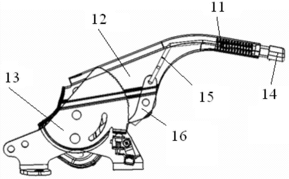
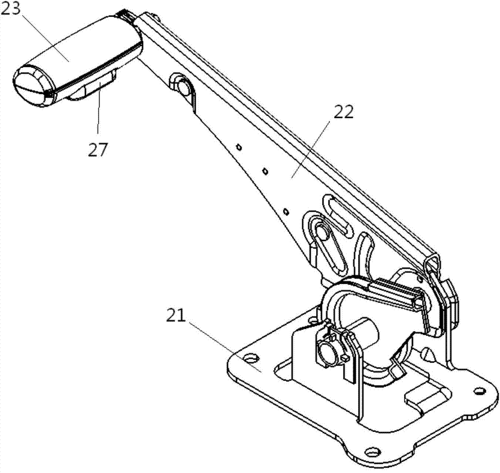
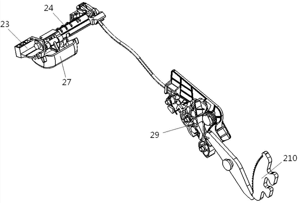
[0039] Such as Figure 2-8 As shown, a parking control handle provided by the embodiment of the present invention includes a base 21, a rotating handle 22 and a transmission mechanism. One end of the rotating handle 22 is rotationally connected with the base 21, and the other end of the rotating handle 22 is fixed with a horizontal handle 23. The transmission mechanism includes a rotating shaft 24, a button 27, a drag cable 28, a rotating member 29 and a ratchet plate 210, the rotating shaft 24 is connected to the horizontal handle 23 in rotation, and the first rocking arm 25 and the second rocking arm are respectively provided at its two ends 26, wherein the second rocker arm 26 is located in the rotating handle 22; the button 27 is fixed on the...


PUM


Abstract

The invention discloses a parking control handle and an automobile. The parking control handle comprises a base, a rotating handle and a transmission mechanism. One end of the rotating handle is rotatably connected with the base, and a horizontal handle is fixed to the other end of the rotating handle. The transmission mechanism comprises a rotating shaft, a button, an inhale cable, a rotating piece and a ratch plate. The rotating shaft is rotatably connected to the horizontal handle, a first rocker arm and a second rocker arm are arranged at the two ends of the rotating shaft respectively, wherein the second rocker arm is located in the rotating handle. The button is fixed to the first rocker arm, and one part of the button protrudes out the horizontal handle. The inhale cable is located in the rotating handle, and one end o the inhale cable is fixed to the second rocker arm. The rotating piece is rotatably connected to the base, and one end of the rotating piece is connected with the inhale cable. The ratch plate is located at the moving distance of the rotating piece. Compared with a straight-holding rotating handle in the prior art, the force origin of the horizontal handle can fall on the tail end of the rotating handle, and in a same scale space, the horizontal handle can provide a grater lever ratio than the straight-holding rotating handle.

Description

technical field [0001] The invention relates to automobile technology, in particular to a parking control handle and an automobile. Background technique [0002] The parking brake mechanism of the car (commonly known as the hand brake) is used to stop the car in place when parking. The parking brake mechanism generally includes a parking handle, a parking cable and a parking brake. The parking handle applies the parking force to the parking cable, and the parking cable transmits the parking force to the parking brake to complete the parking brake. [0003] figure 1 It is a structural schematic diagram of the parking handle in the prior art; figure 1 As shown, the parking handle includes a handle body 11, a rotating handle 12, a ratchet plate 13, a button 14, a push rod 15 and a pawl 16. The rotating handle 12 is arranged on the handle body 11, and the rotating handle 12 includes two oppositely arranged The plate, the ratchet plate 13 is arranged between the two plates of ...

Claims


Application Information

Patent Timeline
Patent Type & Authority Applications(China)
IPC IPC(8): B60T7/10
CPCB60T7/101
Inventor 应卓凡吴桂宝董良胡磊张岩朱砂储军高波
Owner ANHUI JIANGHUAI AUTOMOBILE GRP CORP LTD
Why Eureka
Try Eureka