Synchronizers for transmissions

A technology for synchronizers and transmissions, applied to clutches, mechanically driven clutches, mechanical equipment, etc., to achieve the effects of saving weight, increasing durability, and saving costs

Active Publication Date: 2019-07-12
HYUNDAI MOTOR CO LTD
View PDF1 Cites 0 Cited by
  • Summary
  • Abstract
  • Description
  • Claims
  • Application Information

AI Technical Summary

Problems solved by technology

[0011] However, this synchronizer cannot solve the above problems

Method used


Image

  • Synchronizers for transmissions
  • Synchronizers for transmissions
  • Synchronizers for transmissions

Examples


Embodiment Construction

[0030] Reference will now be made in more detail to preferred embodiments of the invention, an example of which is shown in the accompanying drawing. Wherever possible, the same reference numbers will be used throughout the drawings and the specification to refer to the same or like parts.

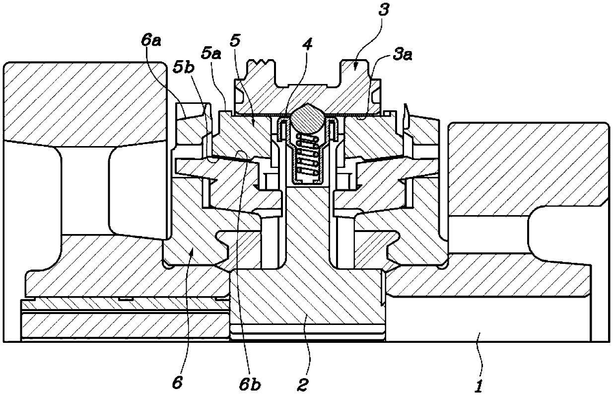
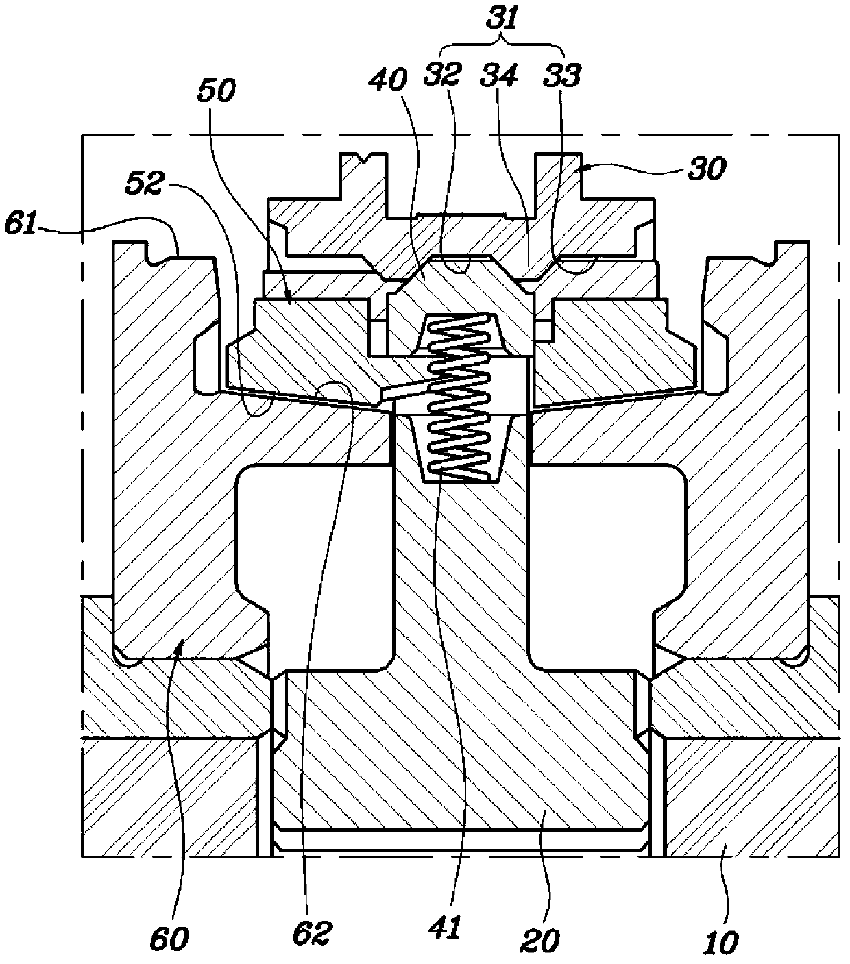
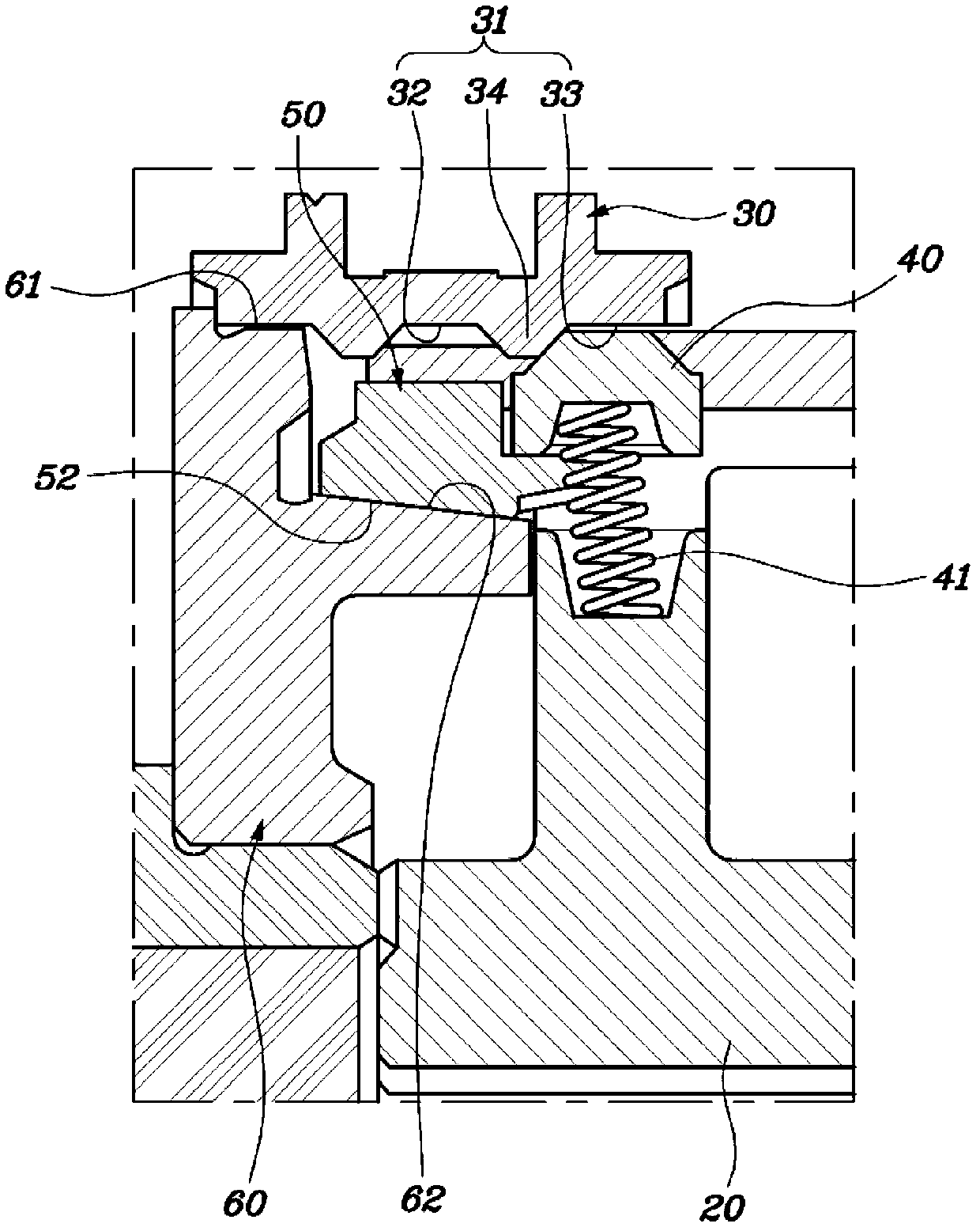
[0031] figure 2 A view showing the structure of a synchronizer for a transmission according to the present invention in a state before its synchromesh; image 3 is a view showing the structure of a synchronizer for a transmission according to the present invention in a state after its synchronous engagement; and Figure 4 is a view of the shape of the shift gear 31 formed on the inner circumference of the sleeve 30 in the synchronizer, wherein the teeth of the shift gear have different thicknesses;

[0032] refer to Figures 2 to 4 A synchronizer for a transmission according to the present invention generally includes a sleeve 30 , a synchronization key 40 , a synchronizer lock ring 50...


PUM


Abstract

The invention discloses a synchronizer for a transmission. The synchronizer includes a sleeve with shift gears. A synchro key is provided to the hub so as to protrude toward the sleeve. A synchronizer ring is arranged around the circumference of the hub. A transmission gear is freely rotatably disposed about the synchronizer ring and has a clutch gear circumferentially facing the sleeve. The shift gear has different tooth thicknesses based on a contact state with respect to the synchro key such that the shift gear comes into contact with the synchro key with a tooth thickness greater than that of the shift gear not in contact with the synchro key. The tooth thickness at which the synchronous key makes contact.

Description

technical field [0001] The present invention relates generally to a synchronizer for a transmission, and more particularly to a synchronizer for a transmission in which the shape of the sleeve teeth is altered to reduce the pressure exerted on the surfaces of the synchronizer keys, and Reduced travel of the sleeve for easier lever operation and the ability to remove the stop pin, saving cost and weight of the synchronizer. Background technique [0002] Generally speaking, a synchronizer for a transmission is a part of a synchronous manual transmission that is manipulated and driven by a transmission lever through a transmission mechanism to respectively control the rotational speed of a pair of transmission gears provided on the input shaft and the output shaft (RPM) to allow the pair of gears to mesh smoothly, thereby preventing the transmission from being jolted. [0003] refer to figure 1 , the synchronizer is configured such that its hub 2 is coupled to the rack of the...

Claims


Application Information

Patent Timeline
Patent Type & Authority Patents(China)
IPC IPC(8): F16D23/06
CPCF16D23/06F16D2023/0618F16D2023/0662
Inventor 朴钟闰渔顺基
Owner HYUNDAI MOTOR CO LTD
Why Eureka
Try Eureka