Electric lock comprising actuating device for motor vehicle lock

A technique for actuating devices and motor vehicles, applied in the direction of electric locks, electric car locks, power transmission/actuator features, etc., can solve the problem that the release mechanism cannot provide locking devices, etc.

Active Publication Date: 2018-04-17
KIEKERT AG
View PDF10 Cites 0 Cited by
  • Summary
  • Abstract
  • Description
  • Claims
  • Application Information

AI Technical Summary

Problems solved by technology

[0006] In extreme cases or in adverse weather conditions, which may result, much greater forces are applied to the locking device, so that the usual release mechanism cannot provide sufficient force to open the locking device

Method used


Image

  • Electric lock comprising actuating device for motor vehicle lock
  • Electric lock comprising actuating device for motor vehicle lock

Examples


Embodiment Construction

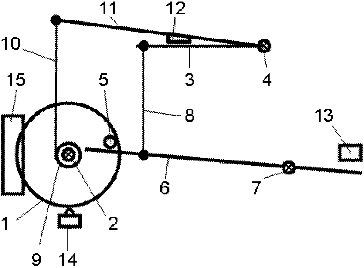
[0021] figure 1 An actuating device is shown schematically by means of which, for example, a locking pawl can be opened. An actuator 1 is shown, which can essentially be a wheel or a disc mounted rotatably via a shaft 2 . The pawl 3 can be moved out of its locking position by a rotation of the actuator 1 , in particular by a rotation in the counterclockwise direction about its axis 4 . The force for moving pawl 3 out of its locking position depends on the direction of rotation of actuator 1 . If the actuator 1 is turned in a clockwise direction about its axis 2, the actuator pin 5 mounted on the wheel on the edge side catches the rod end of the release lever 6 and thus causes the release lever 6 to rotate in an anticlockwise direction about its axis 7 swing. The actuator pin is also used as driver. This pivoting movement of the release lever 6 is transmitted to the locking pawl 3 , for example due to a lever 8 which is fastened on the one hand to the release lever 6 and on...


PUM


Abstract

The aim of the invention is to be able to constantly open a locking mechanism of an electrically actuated lock of a motor vehicle with sufficiently large force, without having to provide an excessively large electric motor and / or an excessively large gearing transmission ratio for this purpose. In order to solve the problem, a lock for a motor vehicle comprises a locking mechanism (3) and an actuator device for opening the locking mechanism (3). The actuation device comprises a rotatable actuator (1) which can be rotated by a motorised drive (15), in particular by an electric drive. A rotatingof the actuator (1) brings about an unlocking, i.e. an opening, of the locking mechanism (3). The locking mechanism (3) can be opened independently of the direction of rotation of the actuator (1). Opening of the locking mechanism (3) is therefore not dependent upon a defined direction of rotation. The force with which the locking mechanism (3) is opened depends on the direction of rotation of the actuator (1). Opening can therefore be achieved with different force depending on the direction of rotation. In this way, in regular operation opening is possible with a lower force compared to a case requiring a greater force for opening. In regular operation, in which a conventional force is used for opening the locking mechanism (3), opening is achieved quickly and with low expenditure of energy. However, it is still possible, if necessary, albeit with delay, to be able to open with greater force for this purpose.

Description

technical field [0001] The invention relates to a lock with an actuating device for a door or hatch of a motor vehicle. Background technique [0002] Such a lock has a locking device / locking mechanism which in principle comprises a rotary locking fork and a locking pawl for locking the rotary locking fork in the locking position and, alternatively, a locking pawl for locking the locking pawl in its locking position. in the deadlock lever. Such a lock is known from document DE 102009026921 A1. [0003] The actuating device serves to open the door or hatch and thus enables unlocking of the locking device. The actuation of the actuating device causes the locking pawl and, if necessary, the locking lever to leave its locking position, finally opening the locking device. The door or hatch can then be opened. [0004] The actuating device usually has a release lever, which is actuated in order to open or unlock the locking device. Such a release lever is generally connected t...

Claims


Application Information

Patent Timeline
Patent Type & Authority Applications(China)
IPC IPC(8): E05B81/14E05B77/10E05B81/06E05B79/20E05B81/34
CPCE05B79/20E05B81/06E05B81/14E05B81/34E05B77/10
Inventor H·施弗尔
Owner KIEKERT AG
Why Eureka
Try Eureka