Spin-free stepless transmission unit

A continuously variable speed unit, non-spin technology, applied in the direction of friction transmission, belt/chain/gear, mechanical equipment, etc., can solve the problems of reduced traction efficiency, softening of workpiece surface, rising oil temperature, etc., to achieve no spin EFFECT OF EFFICIENCY LOSS

Active Publication Date: 2015-07-15
SICHUAN UNIV
View PDF12 Cites 31 Cited by
  • Summary
  • Abstract
  • Description
  • Claims
  • Application Information

AI Technical Summary

Problems solved by technology

[0003] The disadvantage is that these two toroidal continuously variable transmission units cannot avoid the loss of "spin" efficiency under most wo...

Method used


Image

  • Spin-free stepless transmission unit
  • Spin-free stepless transmission unit
  • Spin-free stepless transmission unit

Examples


Embodiment Construction

[0017] The present invention will be further described in detail below in conjunction with the accompanying drawings and specific embodiments.

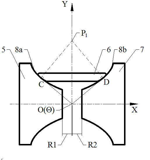
[0018] Due to the special curved surface shape of the non-spin stepless transmission unit, the main components in the transmission unit need to adjust their positions during the speed adjustment process, so a state must be determined to determine the origin position. When the transmission ratio is 1, the position of each component in the entire transmission unit is relatively special, so for the convenience of description, the transmission state diagram of the non-spin continuously variable transmission unit when the transmission ratio is 1 is in figure 2 shown in . The non-spin input cone 5 and the non-spin roller 6 are pressed tightly on the contact point C, and the non-spin output cone 7 and the non-spin roller 6 are pressed tightly on the contact point D, forming The oil film transmits power by the rotation of each component. P...


PUM


Abstract

The invention discloses a spin-free stepless transmission unit and aims to provide a spin-free stepless transmission unit which can avoid loss of spin efficiency in certain range of gear ratio. The spin-free stepless transmission unit comprises a spin-free input cone disc (5), a spin-free output cone disc (7) and a spin-free idler wheel (6) which are pressed and in contact by means of clamping force; power is transmitted by traction; speed regulation is realized by swinging the idler wheel by a certain angle; generatrices of rotating curved surfaces of the spin-free input cone disc (5) and the spin-free output cone disc (7) are a logarithmic curve. In a speed regulation process, the rotating axes of the spin-free input cone disc (5), the spin-free output cone disc (7) and the spin-free idler wheel (6) of the spin-free stepless transmission unit and a common tangent of contact points are intersected at one point. The spin-free stepless transmission unit is used for replacing stepless transmission units in various annular stepless transmissions.

Description

technical field [0001] The invention relates to a transmission unit in a transmission system, specifically a traction type continuously variable transmission unit. Background technique [0002] Traction-type full toroidal CVTs and traction-type semi-toroidal CVTs have been partially loaded and put into the market, such as Chinese patent publication numbers CN 101479503B, CN 100460715C, CN 1116536C, CN 102725561B and CN 101156006A all disclose This type of continuously variable transmission. The main components of the transmission unit are: input shaft, axial loading device, input cone, drive roller, output cone, and output shaft. The principle is to rely on the traction performance of the traction oil in the contact area of ​​the input disc, drive roller and output disc. Transmission of motion and power, this design improves the friction conditions between the contact surfaces, increases the load-carrying capacity, and is suitable for medium and large-displacement cars. ...

Claims


Application Information

Patent Timeline
IPC IPC(8): F16H15/38F16H37/02
CPCF16H15/38F16H2015/383
Inventor 李青涛李华姚进
Owner SICHUAN UNIV
Why Eureka
Try Eureka