A kind of non-spin stepless transmission and its speed regulating device

A technology of continuously variable transmission and speed regulating device, which is applied in the direction of transmission device, friction transmission device, belt/chain/gear, etc. It can solve the problems of complex control and achieve the effect of simple control mode and no loss of spin efficiency

Active Publication Date: 2017-06-16
SICHUAN UNIV
View PDF5 Cites 0 Cited by
  • Summary
  • Abstract
  • Description
  • Claims
  • Application Information

AI Technical Summary

Problems solved by technology

[0005] The disadvantage of this continuously variable transmission unit is that in the process of speed regulation, in addition to the rollers needing to swing at a certain angle, the positions of the rollers, input cones and output cones all need to be adjusted, which makes the control complicated.

Method used


Image

  • A kind of non-spin stepless transmission and its speed regulating device
  • A kind of non-spin stepless transmission and its speed regulating device
  • A kind of non-spin stepless transmission and its speed regulating device

Examples


Embodiment Construction

[0012] The present invention will be further described in detail below in conjunction with the accompanying drawings and specific embodiments.

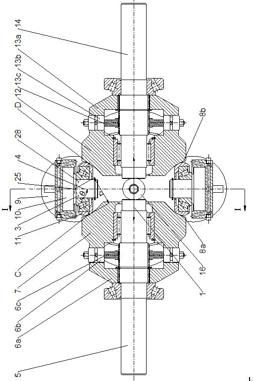
[0013] figure 1 The main sectional view of the non-spin continuously variable transmission is shown. As shown in the figure, in this scheme, an input shaft cam 6a is installed on the input shaft 5, and the input shaft cam 6a, the input shaft cam roller 6b, and the input shaft roller frame 6c form an input shaft axial pressure device. To provide axial force to the non-spin input cone 7 to ensure that it maintains pressure contact with the non-spin roller 11 at the input point C, the non-spin roller 11 is installed on the roller shaft 10, and the roller shaft 10 is fixedly installed On the trunnion 9, it can finally ensure that the position of the non-spin roller 11 relative to the trunnion 9 remains fixed, and the non-spin roller 11 can still rotate around its own roller rotation axis 4; on the other side, the output shaft 14 is equip...


PUM


Abstract

The invention discloses a non-spinning continuously variable transmission and a speed regulation device thereof, and aims at providing a continuously variable transmission capable of avoiding spinning efficiency loss within a certain range of variable-speed ratio. The non-spinning continuously variable transmission comprises an input shaft, an input shaft axial pressurizing device, an input cone disc, rollers, an output cone disc, an output shaft axial pressurizing device and an output shaft; the input cone disc and the output cone disc are respectively in contact with the rollers in a compression manner, and power is transmitted by means of traction; each of generatrices of the surface of revolution of the input cone disc and the surface of revolution of the output cone disc is a logarithmic curve; the rollers are arranged on a trunnion; by limiting the displacement of trunnion sliders, fixed points of the rollers only can move along the radial direction of the cone disc; center rings are respectively processed at two ends of the trunnion according to the distance position requirement; through the changes of the positions of central sliders, positions of the trunnion and the rollers and a swinging angle are adjusted, and therefore the goal of simple speed regulation is achieved; meanwhile, the input cone disc and the output cone disc respectively need to move along the own axis of rotation during speed regulation.

Description

technical field [0001] The invention relates to a transmission device in the mechanical field, specifically a traction type continuously variable transmission. Background technique [0002] Traction-type full toroidal CVT and traction-type semi-toroidal CVT have been partially loaded and put into the market, as Chinese patent publication numbers CN 101479503B, CN 100460715C, CN 1116536C, CN102725561B and CN 101156006A all disclose this Types of continuously variable transmissions. The main components of this type of transmission are: input shaft, axial loading device, input cone, drive roller, output cone, and output shaft. Performance to transmit motion and power, this design improves the friction conditions between the contact surfaces, increases the carrying capacity, and is suitable for medium and large displacement cars. [0003] These two kinds of continuously variable transmissions: traction full toroidal continuously variable transmission and traction semi toroidal...

Claims


Application Information

Patent Timeline
IPC IPC(8): F16H15/38
CPCF16H15/38
Inventor 李青涛李华姚进
Owner SICHUAN UNIV
Why Eureka
Try Eureka