
Built-in channel thermal evaporator and solar water heater with the thermal evaporator

A solar water heater and evaporator technology, which is applied to solar thermal collectors, solar thermal collectors using working fluids, solar thermal energy, etc., can solve problems such as hidden safety hazards, large heat loss, and unfavorable energy conservation.

Inactive Publication Date: 2017-10-27
ZHENGZHOU UNIV
View PDF13 Cites 0 Cited by
  • Summary
  • Abstract
  • Description
  • Claims
  • Application Information

AI Technical Summary

Problems solved by technology

[0003] Traditional integrated solar water heaters can meet the needs of low-rise buildings. However, the roofs of medium and high-rise buildings, especially high-rise buildings, are not suitable for installing traditional solar water heaters. They cannot meet the requirements of integration with medium and high-rise buildings and affect the aesthetics of buildings. Security risks
In order to solve the above problems, people are working hard to study split solar water heaters. The heat collecting evaporator and the water storage tank are connected by pipes, but the water storage tank still needs to be installed outdoors. Internal and external transportation, there are problems such as large heat loss and low solar energy conversion efficiency, and it needs to rely on gravity to provide the power of the system cycle. The power to provide the system cycle needs to consume electric energy, which is not conducive to saving energy

Method used


Image

  • Built-in channel thermal evaporator and solar water heater with the thermal evaporator
  • Built-in channel thermal evaporator and solar water heater with the thermal evaporator
  • Built-in channel thermal evaporator and solar water heater with the thermal evaporator

Examples


Embodiment 1

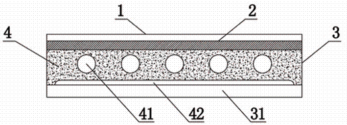
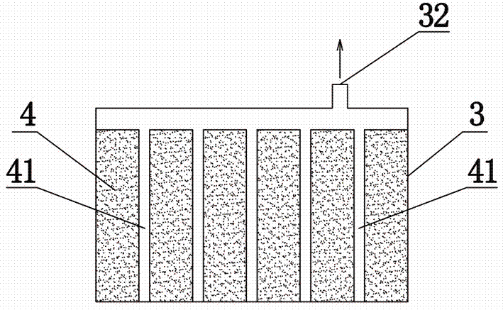
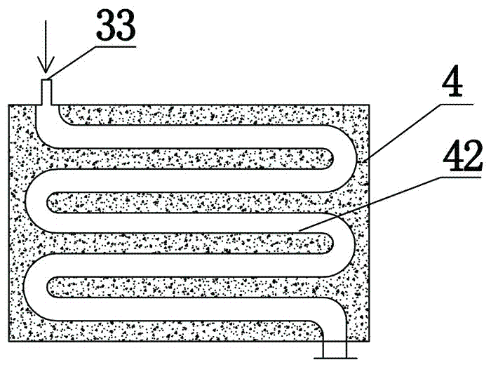
[0023] Such as figure 1 , figure 2 and image 3 As shown, a heat collecting evaporator with a built-in channel includes a thermal insulation shell 3 and an airtight shell arranged inside the thermal insulation shell 3. The shell structure enables the entire heat collecting evaporator to be made into a plate structure, which is suitable for High-rise building installation requirements; the entire solar collector plate is set in a plate type, which is convenient for installing the entire heat collector evaporator on the outer wall of a mid-to-high-rise building, and the overall appearance is beautiful.

[0024] An insulation layer 31 is arranged between the bottom of the airtight casing and the heat-insulating shell 3, and the insulation layer 31 can be arranged to wrap the airtight casing as required, and not cover the upper part of the airtight casing to ensure the absorption of solar heat The upper cover of the airtight housing is provided with a glass cover plate 1, and t...

Embodiment 2

[0031] Such as Figure 4 and Figure 5 As shown, a heat collecting evaporator with a built-in channel includes a thermal insulation shell 3 and an airtight shell arranged inside the thermal insulation shell 3. The shell structure enables the entire heat collecting evaporator to be made into a plate structure, which is suitable for High-rise building installation requirements; the entire solar collector plate is set in a plate type, which is convenient for installing the entire heat collector evaporator on the outer wall of a mid-to-high-rise building, and the overall appearance is beautiful.

[0032] An insulation layer 31 is arranged between the bottom of the airtight casing and the heat-insulating shell 3, and the insulation layer 31 can be arranged to wrap the airtight casing as required, and not cover the upper part of the airtight casing to ensure the absorption of solar heat The upper cover of the airtight housing is provided with a glass cover plate 1, and the glass co...

Embodiment 3

[0039] Such as Figure 6 As shown, a solar water heater includes a heat collecting evaporator 6, a water storage tank 8, a condenser 9 arranged in the water storage tank 8, and a loop pipeline 7, thereby forming a split solar water heater, which is suitable for middle and high-rise buildings building needs. The gas-phase outlet of the heat-collecting evaporator 6, the loop pipe 7, the inlet and outlet of the condenser 9 and the liquid-phase inlet of the heat-collecting evaporator 6 are sequentially connected to form a heat circulation delivery loop.

[0040] The heat-collecting evaporator 6 used in this embodiment is the flat-plate heat-collecting evaporator in the above-mentioned embodiment 1 or embodiment 2, and the circulation of the heat circulation conveying circuit can carry out the circulating conveying of the working medium without other power. Specific working principle: use the heat collecting evaporator 6 to absorb solar radiation, heat the liquid working medium in...


PUM


Abstract

The invention provides a heat collection evaporator with a built-in passage. The heat collection evaporator comprises a heat preservation shell and a sealed shell, wherein the sealed shell is arranged in the heat preservation shell; a heat preservation layer is arranged between the bottom part of the sealed shell and the heat preservation shell; the upper part of the sealed shell is provided with a glass cover plate; a capillary structure layer and a solar heat collection panel which covers the capillary structure layer are arranged in the sealed shell; a steam collection groove and a working medium backflow groove are prefabricated in the capillary structure layer; a working medium entering the capillary structure layer can be evaporated after heat is absorbed by the solar heat collection plate, so that the heat can be supplied. The invention also provides a solar water heater with the heat collection evaporator, wherein the heat collection evaporator and a water storage tank are communicated through a loop pipeline. According to heat collection evaporator and the solar water heater, provided by the invention, the requirement of mid-rise buildings on the whole attractiveness can be met; meanwhile, power-free cycle of the working medium can be realized by utilizing the capillary action of the capillary structure, the installation of the whole solar water heater is simple, the working medium can be driven without other power, and the daily demands of people can be met.

Description

technical field [0001] The invention relates to a heat collecting evaporator and a solar water heater, in particular to a built-in channel heat collecting evaporator and a solar water heater with the heat collecting evaporator. Background technique [0002] Today, when traditional energy sources such as oil, coal, and natural gas are increasingly tense, in order to protect the environment and achieve sustainable development, it has become a trend to develop new energy and renewable resources. Solar energy has become an important new energy due to its advantages of abundant resources, renewable, no need for mining, transportation, and no pollution. At present, solar water heater technology is the most mature technology and the most widely used solar energy utilization technology in solar heat utilization. [0003] Traditional integrated solar water heaters can meet the needs of low-rise buildings. However, the roofs of medium and high-rise buildings, especially high-rise bui...

Claims


Application Information

Patent Timeline
Patent Type & Authority Patents(China)
IPC IPC(8): F24J2/05F24J2/24F24J2/46F22B1/00F24S10/40F24S10/70
CPCY02E10/44
Inventor 魏新利孟祥睿李光曼张军刘华东
Owner ZHENGZHOU UNIV
Learn More