Duplex image reading apparatus

a reading device and image technology, applied in the direction of corona discharge, printing, instruments, etc., can solve the problems of high cost, unfavorable use of general-purpose image reading devices typified by contact image sensors, and uneven transportation of originals, so as to achieve high resolution, reduce cost, and improve accuracy

Inactive Publication Date: 2006-09-19
CANON KK
View PDF14 Cites 24 Cited by
  • Summary
  • Abstract
  • Description
  • Claims
  • Application Information

AI Technical Summary

Benefits of technology

[0019]The invention according to the present application permits the image reading surface of the first reading means and the image reading surface of the second reading means to be arranged on the substantially same plane with high accuracy, without needs for any complicated mechanism or adjustment, and thus is able to implement cost reduction.
[0020]The invention according to the present application takes up any play or slop in attachment of the second reading means and prevents deviation of the second reading means during transportation of the original, thereby enabling reading in high resolution.
[0021]The invention according to the present application eliminates the moment caused by the frictional force acting on the second reading means and prevents deviation of the second reading means during transportation of the original, thereby enabling reading in high resolution.
[0022]The invention according to the present application permits the static electricity accumulated on the second reading means to be guided to the ground in the main body of the apparatus, without needs for any other additional component, and thus is able to implement cost reduction.
[0023]Since the apparatus is constructed in such structure that the first reading means is fixedly supported while the second reading means is rotatably supported and comprises first abutting means and second abutting means provided at the first reading means and at the second reading means, respectively, and arranged in contact with each other outside an original transportation region; reading urging means for urging the second reading means in a direction in which the second abutting means abuts against the first abutting means; a first white reference disposed at a position opposite to the first reading means so that the original is urged toward an image reading surface of the first reading means, the first white reference having white color as a color reference of the first reading means; and a second white reference disposed at a position opposite to the second reading means so that the original is urged toward an image reading surface of the second reading means, the second white reference having white color as a color reference of the second reading means, the apparatus is able to readily regulate the positional relation between the reading means even in use of the inexpensive reading means and effect stable transportation performance and duplex reading performance with high quality.
[0024]The image reading apparatus of the present invention is able to reduce the static electricity on the original so as to stabilize the original transportation performance and prevent malfunctions and breakage of the image reading means.

Problems solved by technology

In the former conventional example (Japanese Patent Application Laid-Open No. 2000-115452) described above, however, the positional relation between the two image reading devices was greatly associated with the transportation performance of an original and there was the drawback that, particularly, when two image reading surfaces were not parallel but inclined, the original was not smoothly transported, so as to cause an original jam.
In order to avoid it, it was necessary to apply severe dimensional accuracy to components and provide means of provision of an adjusting mechanism, which was the cause of cost increase.
In the foregoing latter conventional example (Japanese Patent Application Laid-Open No. 10-190938), since the apparatus was applied to the image reading apparatus, such as facsimile machines and image scanners, the structure did not allow use of general-purpose image reading devices typified by contact image sensors.
For this reason, it was necessary to fabricate dedicated image reading devices, but it must raise the cost considerably.

Method used


Image

  • Duplex image reading apparatus
  • Duplex image reading apparatus
  • Duplex image reading apparatus

Examples


first embodiment

(First Embodiment)

[0041]The first embodiment of the present invention will be described below on the basis of FIGS. 1 to 3.

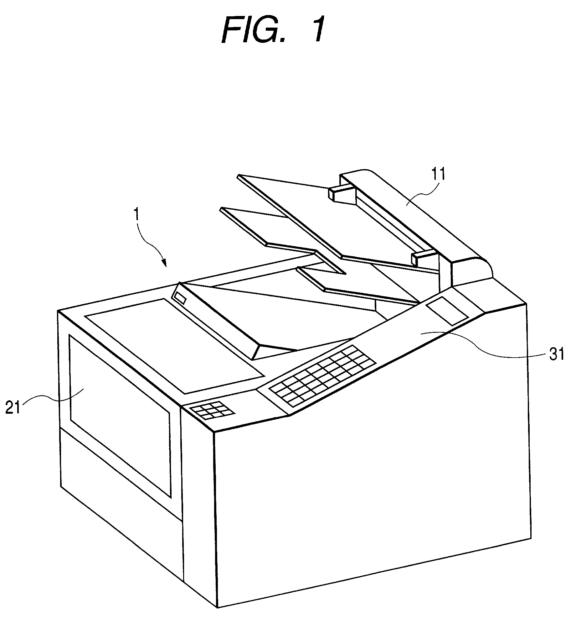
[0042]FIG. 1 is a perspective view of a facsimile machine showing the first embodiment of the present invention.

[0043]In FIG. 1, the facsimile machine 1 is comprised of a reading section 11 for reading an original S, a recording section 21 for recording an image read by the reading section 11, or a received image on a recording sheet, an operation section 31 for permitting the user to operate the machine, and a control section, not shown, for controlling sending / receiving, and copy operations. The duplex image reading apparatus of the present invention is applied to the reading section 11.

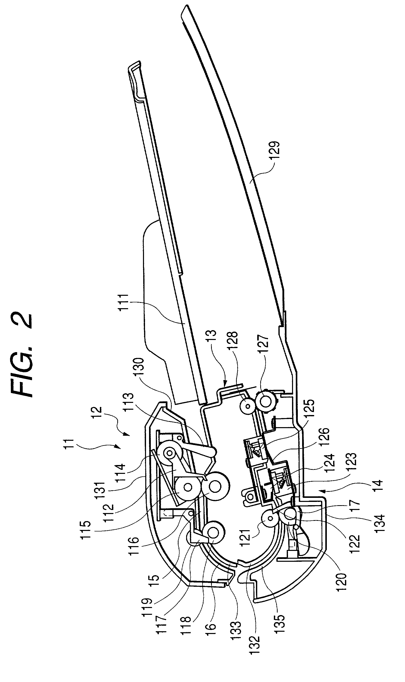
[0044]FIG. 2 is a cross-sectional view of the reading section 11 to which the duplex image reading apparatus is applied, and the structure and operation of the reading section 11 will be described below with reference to FIG. 2.

[0045]The operator sets originals S on an original...

second embodiment

(Second Embodiment)

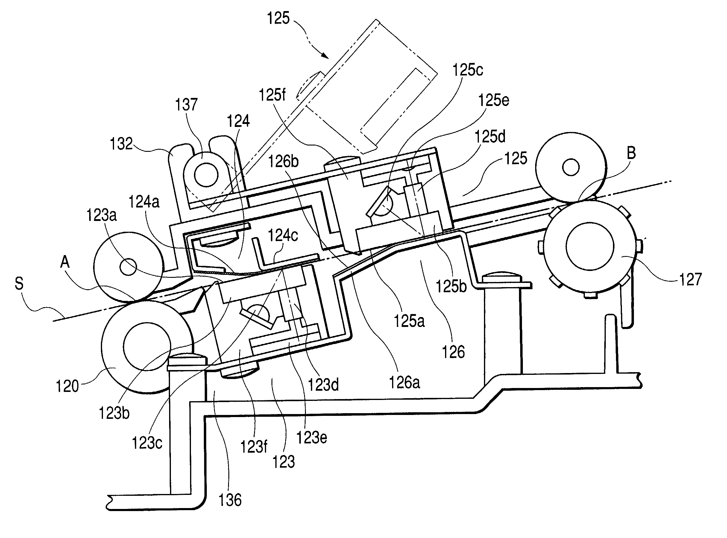
[0072]FIG. 5 is a partially enlarged view of the back side reading portion 125 showing the second embodiment of the present invention.

[0073]In FIG. 5, the sensor housing 125f of the back side reading portion 125 is arranged so that the sensor housing 125f is elastically supported so as to be displaceable in the direction substantially perpendicular to the image reading surface 125a, by an electroconductive leaf spring 138 connected to the ground (not shown) in the main body of the apparatus so that the image reading surface 125a is urged against the back side white reference 126.

[0074]As this structure has no play or slop in between the fitting portions, as compared with the supporting methods as shown in FIGS. 3 and 4, the back side reading portion 125 is prevented from deviating in the transporting direction, and it is thus feasible to implement reading in high resolution.

[0075]Further, static electricity is generated by the friction between the image reading su...

third embodiment

(Third Embodiment)

[0076]FIG. 7 is a partially enlarged view of the back side reading portion 125 showing the third embodiment of the present invention.

[0077]In FIG. 7, the sensor housing 125f of the back side reading portion 125 is constructed in such structure that the housing is elastically supported so as to be displaceable in the direction substantially perpendicular to the image reading surface 125a, by an electroconductive leaf spring 139 connected to the ground in the main body of the apparatus not shown and that the image reading surface 125a is urged against the back side white reference 126.

[0078]The leaf spring 139 is connected and supported on the almost same plane as the image reading surface 125a, which achieves the following effect.

[0079]Namely, during transportation of the original S, the friction between the image reading surface 125a and the original S produces a frictional force F toward the downstream in the transporting direction, but this frictional force F is ...


PUM


Abstract

A duplex image reading apparatus has a transportation path for transporting a sheet original to a reading region by an original transporting device, and first and second reading devices placed corresponding to respective transportation sides of the sheet original in the reading region of the transportation path, and is constructed in such structure that each of the first and second reading devices is of such a configuration that a color reference portion used as a color reference for reading is opposed to a reading portion while the color reference portion and the reading portion are placed on two sides with the transportation sides of the sheet original in between, wherein the first and second reading devices are arranged so that either one of the reading portion and the color reference portion is supported so as to be movable in a direction substantially perpendicular to an image reading surface of the reading portion.

Description

BACKGROUND OF THE INVENTION[0001]1. Field of the Invention[0002]The present invention relates to duplex image reading apparatus for reading images on two sides of an original transported by original transporting means.[0003]2. Description of Related Art[0004]Among conventional duplex image reading apparatus is one proposed in such structure that two image reading devices are arranged in a fixed state on respective sides of a bent transportation path, as described in Japanese Patent Application Laid-Open No. 2000-115452.[0005]There is another apparatus proposed in such structure that two image reading devices are arranged at positions almost opposite to each other, one image reading device is fixed, and the other image reading device is urged against the fixed image reading device, as described in Japanese Patent Application Laid-Open No. 10-190938.[0006]In the former conventional example (Japanese Patent Application Laid-Open No. 2000-115452) described above, however, the positional...

Claims


Application Information

Patent Timeline
Patent Type & Authority Patents(United States)
IPC IPC(8): H04N1/04G03G15/00H04N1/12H04N1/193H04N1/203
CPCH04N1/2032H04N1/203H04N1/121H04N1/193H04N2201/044G03G15/00
Inventor HASEGAWA, KAZUHIKOSAWADA, HIROHISA
Owner CANON KK
Why Eureka
Try Eureka