A lead belt storage and discharge device
A technology of unwinding device and lead belt, which is applied in the direction of thin material handling, transportation and packaging, winding strips, etc., can solve the problems affecting the production efficiency of the grid, and achieve the effect of improving production efficiency
- Summary
- Abstract
- Description
- Claims
- Application Information
AI Technical Summary
Problems solved by technology
Method used
Image
Examples
Embodiment 1
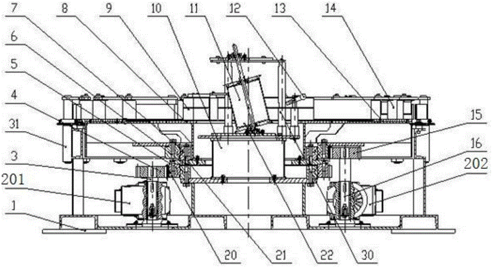
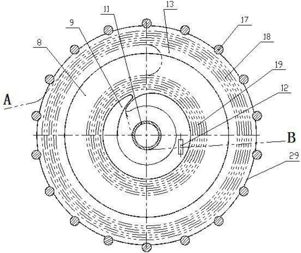
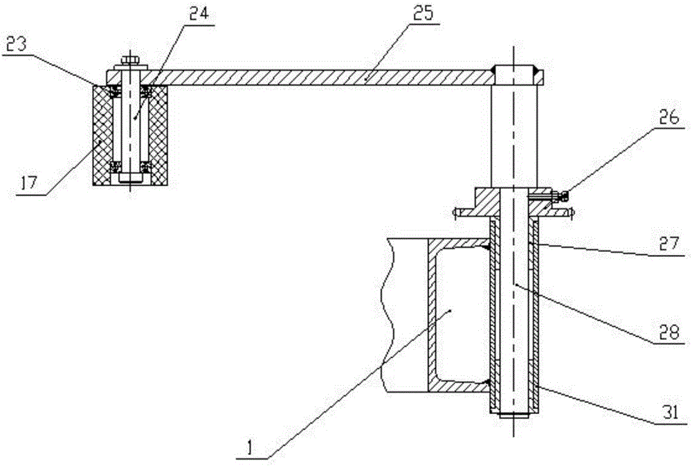
[0023] Such as figure 1 , figure 2 , image 3 As shown, the present invention provides a lead belt storage and discharging device, including a frame 1, a central material guide system 22 fixedly arranged in the center of the frame 1, and a central material guide system 22 located on both sides of the central material guide system 22 and fixed to the frame 1. The connected inner disc rotary system 20 and outer disc rotary system 21, the outer lead coil forming system 14 fixed on the frame 1, the central material guide system 22 includes a Central material guide frame 10, central material guide frame 10 is fixedly connected with central material guide plate 9 coaxial with central material guide frame 10, central material guide plate 9 is provided with central material guide plate 9 that is movably connected with central material guide frame 10 Roller 11, the lead belt discharge end B of the central material guide plate 9 is provided with a height-adjustable take-up roller 12 ...
Embodiment 2
[0029] On the basis of Embodiment 1, in order to improve the operating efficiency of the lead belt storage and discharging device, the first geared motor 201 and the second geared motor 202 are arranged symmetrically with respect to the central axis of the frame 1 .
Embodiment 3
[0031] On the basis of Embodiment 1, the central material guide plate 9 is fixed on the central material guide frame 10 through the column 30, that is, the central material guide plate 9 is fixed and does not rotate. Since the inner ring of the inner lead tape roll 19 will move close to the central material guide plate 9, it needs to bear a certain torque due to the effect of friction, so the column 30 is selected as the connector.
PUM
 Abstract
Description
Claims
Application Information
 - R&D
- Intellectual Property
- Life Sciences
- Materials
- Tech Scout
- Unparalleled Data Quality
- Higher Quality Content
- 60% Fewer Hallucinations
Browse by: Latest US Patents, China's latest patents, Technical Efficacy Thesaurus, Application Domain, Technology Topic, Popular Technical Reports.
© 2025 PatSnap. All rights reserved.Legal|Privacy policy|Modern Slavery Act Transparency Statement|Sitemap|About US| Contact US: help@patsnap.com


