Display panel and display device

A display panel and substrate technology, applied in the direction of diodes, instruments, semiconductor devices, etc., can solve the problems of high energy consumption of display devices, high energy consumption of backlight sources, and poor display quality

Inactive Publication Date: 2015-07-22
BOE TECH GRP CO LTD
View PDF11 Cites 4 Cited by
  • Summary
  • Abstract
  • Description
  • Claims
  • Application Information

AI Technical Summary

Problems solved by technology

[0002] At present, liquid crystal display devices can be divided into transmissive liquid crystal display devices and reflective liquid crystal display devices according to the different light sources used. Among them, the transmissive liquid crystal display devices usually need to set a backlight on the back of the liquid crystal display panel to provide illumination, but The high energy consumption of the backlight leads to high energy consumption of the transmissive liquid crystal display device, and when the ambient light is strong, the contrast of the liquid crystal display panel is poor and the display effect is poor, while the reflective liquid crystal display device does not need a backlight source, so it can Low power consumption, more suitable for use in the case of strong ambient light, but its display quality will deteriorate when the ambient light is weak
[0003] The display devices of the above two modes can only have better display quality under specific environmental conditions, and with the improvement of people's requirements for display products, there is an urgent need for a display product that can adapt to different environmental conditions

Method used


Image

  • Display panel and display device
  • Display panel and display device
  • Display panel and display device

Examples


Embodiment Construction

[0028] The specific implementation manners of the present invention will be further described in detail below in conjunction with the accompanying drawings and embodiments. The following examples are used to illustrate the present invention, but are not intended to limit the scope of the present invention.

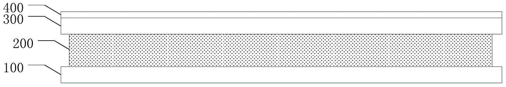
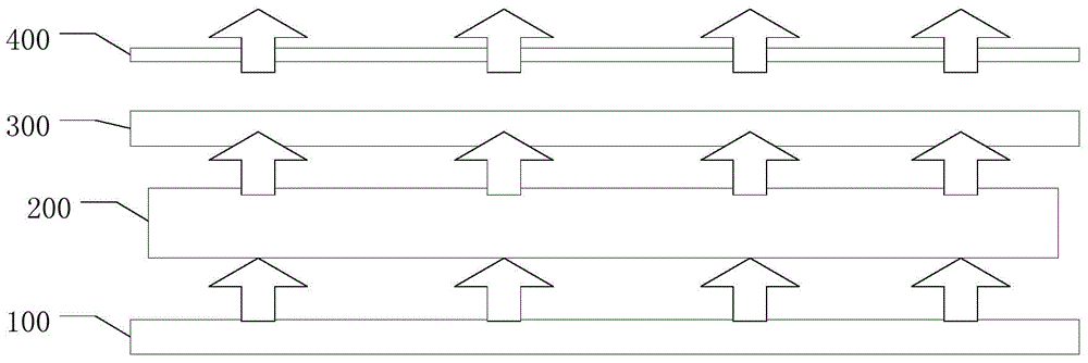
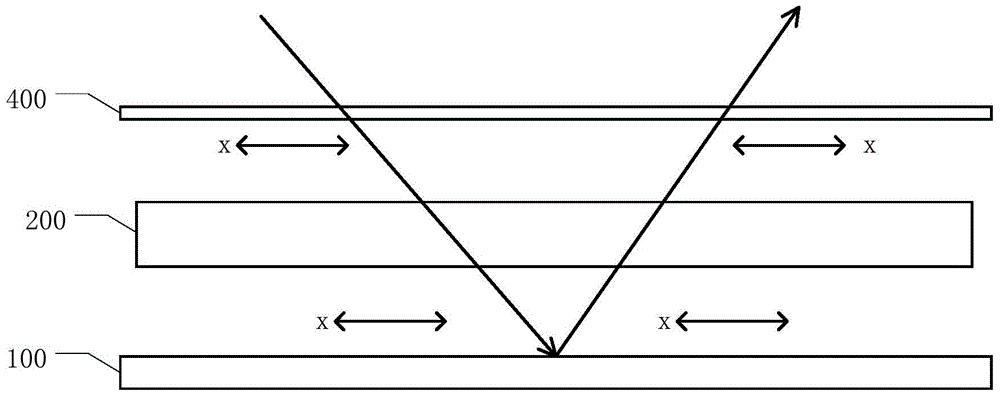
[0029] An embodiment of the present invention provides a display panel, which includes a first substrate, a liquid crystal layer, a second substrate, and a polarizer that are sequentially stacked;

[0030] A light reflective layer and a plurality of organic light emitting units are disposed on the first substrate, and the plurality of organic light emitting units are located on a side of the light reflective layer close to the liquid crystal layer;

[0031] The second substrate is used to control the deflection of liquid crystal molecules in the liquid crystal layer, and is divided into a plurality of sub-pixel regions.

[0032] The display panel provided by the embodimen...


PUM


Abstract

The invention provides a display panel and a display device. The display panel comprises a first base panel, a liquid crystal layer, a second base panel and a polarizing film which are arranged in sequence in a stacked mode; a reflecting layer and multiple organic light-emitting units are arranged on the first base panel, and the multiple organic light-emitting units are located at the side, close to the liquid crystal layer, of the reflecting layer; the second base panel is used for controlling the eccentric rotation of liquid crystal molecules in the liquid crystal layer, and the second base panel is divided into multiple sub-pixel areas. According to the display panel, when a display signal is input in the first base panel, the transmission-type display of the display panel can be achieved, and when the display signal is input in the second base panel, the reflection-type display of the display panel can be achieved.

Description

technical field [0001] The present invention relates to the display field, in particular to a display panel and a display device. Background technique [0002] At present, liquid crystal display devices can be divided into transmissive liquid crystal display devices and reflective liquid crystal display devices according to the different light sources used. Among them, the transmissive liquid crystal display devices usually need to set a backlight on the back of the liquid crystal display panel to provide illumination, but The high energy consumption of the backlight leads to high energy consumption of the transmissive liquid crystal display device, and when the ambient light is strong, the contrast of the liquid crystal display panel is poor and the display effect is poor, while the reflective liquid crystal display device does not need a backlight source, so it can Low power consumption, more suitable for use in the case of strong ambient light, but its display quality wil...

Claims


Application Information

Patent Timeline
Patent Type & Authority Applications(China)
IPC IPC(8): G02F1/1335G02F1/1347G02F1/139
CPCG02F1/133603G02F1/133605G02F1/133606G02F1/133613G02F1/1335G02F1/133555G02F1/1347G02F1/133531G02F1/133567G02F1/133626H10K50/818H10K59/12H10K59/50G02F1/133528G02F1/133553G02F1/134363G02F1/1368G02F2201/44
Inventor 赵利军
Owner BOE TECH GRP CO LTD
Why Eureka
Try Eureka