Sliding mechanism for vacuum cleaner power adjustment

A technology of power adjustment and sliding mechanism, which is applied in the installation of electrical equipment, etc., can solve the problems that the connecting rod 2 is inclined to both sides, it is difficult to ensure the verticality, and the connecting rod 2 is inclined, so as to achieve the effect of solving the cumulative error and virtual position

Active Publication Date: 2017-05-17
SUZHOU CHUNJU ELECTRIC CO LTD
View PDF9 Cites 0 Cited by
  • Summary
  • Abstract
  • Description
  • Claims
  • Application Information

AI Technical Summary

Problems solved by technology

However, since it is difficult to ensure the verticality of the connecting rod 2 and the adjusting block 3 during the installation process, the connecting rod 2 may tilt to both sides, or the connecting rod 2 may be tilted to both sides by constantly moving it during use. There will also be an inclination phenomenon, which will cause the angle deviation of the connecting rod, and the cumulative error will appear during the transmission process, which will cause the slide button transmission compensation of the slider 1 to the potentiometer adjustment rod 41, or problems such as virtual positions.

Method used


Image

  • Sliding mechanism for vacuum cleaner power adjustment
  • Sliding mechanism for vacuum cleaner power adjustment
  • Sliding mechanism for vacuum cleaner power adjustment

Examples


Embodiment Construction

[0028] Preferred embodiments of the present invention will be described in detail below in conjunction with the accompanying drawings.

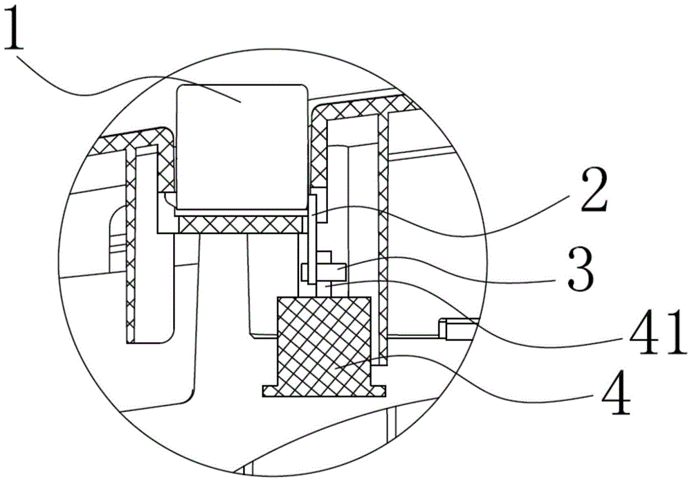
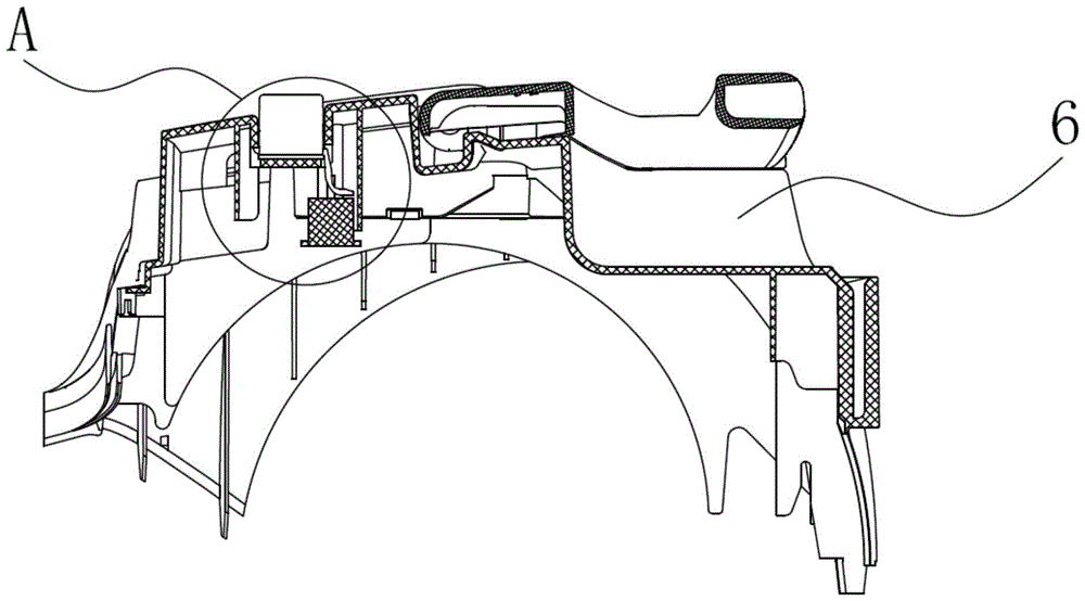
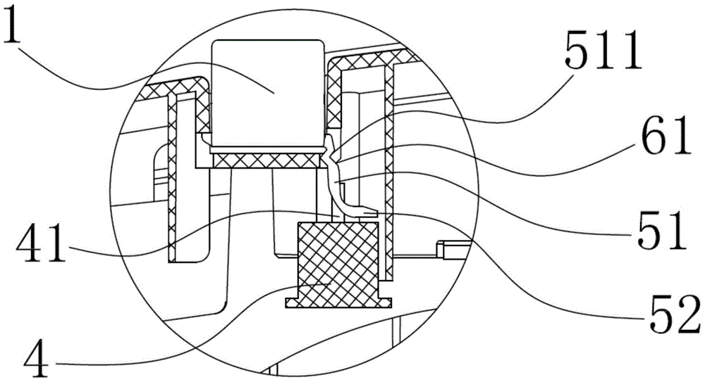
[0029] In order to achieve the purpose of the present invention, as Figure 2-7 As shown, in some embodiments of the sliding mechanism for vacuum cleaner power adjustment of the present invention, it includes a first rod body 51 arranged longitudinally, which is slidably passed through a sliding hole 61 provided on the vacuum cleaner housing 6 Inside, one end of the first rod body 51 extends laterally toward the vacuum cleaner housing 6 to form a second rod body 52, and the second rod body 52 is provided with a through hole 521 along the horizontal direction, and the potentiometer adjusting rod 41 of the potentiometer 4 is passed through. in the through hole 521 . In this mechanism, the rod structure composed of the first rod body and the second rod body replaces the traditional connection structure between the connecting rod and the block b...


PUM


Abstract

The invention discloses a slide mechanism for a dust collector power adjustment. The slide mechanism for the dust collector power adjustment comprises a first rod body arranged lengthways, wherein the rod body is arranged in a slide hole formed in a dust collector housing in a slide mode, one end of the first rod body is extended to the dust collector housing horizontally to form a second rod body, a through hole is form in the second rod body along a horizontal direction, and a potentiometer adjustment rod of a potentiometer is arranged in the through hole. Compared with the prior technology, the slide mechanism for the dust collector power adjustment can effectively solve the problems of cumulative errors and phantoms during an adjustment process.

Description

technical field [0001] The invention relates to an adjustment mechanism for power adjustment on a vacuum cleaner, in particular to a sliding mechanism for power adjustment of the vacuum cleaner. Background technique [0002] In order to form the switch adjustment of the potentiometer on the circuit board in the vacuum cleaner, an adjustment mechanism is generally installed on the current vacuum cleaner, and the adjustment purpose is realized by sliding and driving the potentiometer adjusting rod of the potentiometer. [0003] The current regulatory structure is as follows: figure 1 As shown, it is mainly composed of a slider 1, a connecting rod 2 and an adjusting block 3. One end of the connecting rod 2 is fixedly connected to the sliding button 1, and the other end is fixedly connected to the adjusting block 3, and the adjusting block 3 is adjusted with the potentiometer of the potentiometer 4. The rod 41 is fixedly connected, and by sliding the slide button 1 , the potent...

Claims


Application Information

Patent Timeline
Patent Type & Authority Patents(China)
IPC IPC(8): A47L9/28
Inventor 刘春金
Owner SUZHOU CHUNJU ELECTRIC CO LTD
Why Eureka
Try Eureka