Photovoltaic power generation current-stabilized energy supply method and system
A technology for photovoltaic power generation and current stabilization, which is used in solar thermal power generation, machines/engines, and mechanical power generated by solar energy. It can solve the problems affecting the wide application of photovoltaic power generation and instability.
- Summary
- Abstract
- Description
- Claims
- Application Information
AI Technical Summary
Problems solved by technology
Method used
Image
Examples
Embodiment 1
[0108] A photovoltaic power generation steady current energy supply method, comprising:
[0109] The first step is to convert the electrical energy of the photovoltaic power generation unit 1 into mechanical power;
[0110] In the second step, using the mechanical power to compress and liquefy the air to obtain liquefied air;
[0111] The third step, the liquefied air is stored in the liquefied air storage tank 3;
[0112] In the fourth step, the liquefied air is provided by the liquefied air storage tank 3 to the heated fluid channel of the regenerator 4 to obtain pressurized compressed air;
[0113] In the fifth step, the pressurized compressed air is introduced into the combustion chamber 5, so that the pressurized compressed air and the fuel have a combustion chemical reaction in the combustion chamber 5 to obtain a working fluid;
[0114] In the sixth step, the working fluid is introduced into a series of two or more turbines 6, and the turbine 6 pushes the generator 8 ...
Embodiment 2
[0117] A photovoltaic power generation steady current energy supply system, such as figure 1 As shown, it includes: a photovoltaic power generation unit 1, an air liquefaction unit 2, a liquefied air storage tank 3, a regenerator 4, a combustion chamber 5, a turbine 6 and a generator 8. The photovoltaic power generation unit 1 is responsible for the air liquefaction unit 2. Output power, the liquefied air outlet of the air liquefaction unit 2 is communicated with the inlet of the liquefied air storage tank 3, and the outlet of the liquefied air storage tank 3 is communicated with the inlet of the heated fluid passage of the regenerator 4 , the outlet of the heated fluid channel of the regenerator 4 is communicated with the combustion chamber 5, the working medium outlet of the combustion chamber 5 is communicated with the working fluid inlet of the turbine 6, and the turbine 6 is connected to the The generator 8 outputs power, and the outlet of the working medium of the turbin...
Embodiment 3
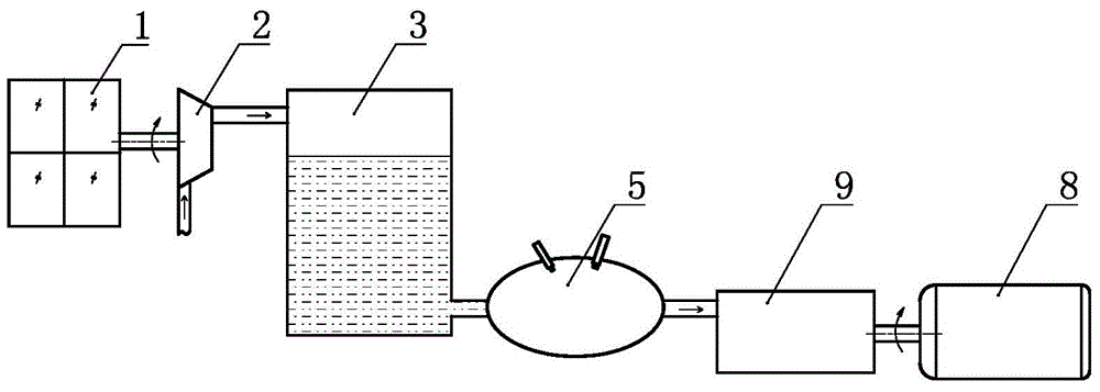
[0119] A photovoltaic power generation steady current energy supply method, comprising:
[0120] The first step is to convert the electrical energy of the photovoltaic power generation unit 1 into mechanical power;
[0121] In the second step, using the mechanical power to compress and liquefy the air to obtain liquefied air;
[0122] The third step, the liquefied air is stored in the liquefied air storage tank 3;
[0123] In the fourth step, the liquefied air is introduced into the combustion chamber 5 from the liquefied air storage tank 3, so that the liquefied air and the fuel have a combustion chemical reaction in the combustion chamber 5 to obtain a working medium;
[0124] In the fifth step, the working medium is introduced into the multi-stage boundary changing fluid mechanism 9, and the multi-stage boundary changing fluid mechanism 9 pushes the generator 8 to output electric power to the outside.
PUM
 Abstract
Description
Claims
Application Information
 - R&D
- Intellectual Property
- Life Sciences
- Materials
- Tech Scout
- Unparalleled Data Quality
- Higher Quality Content
- 60% Fewer Hallucinations
Browse by: Latest US Patents, China's latest patents, Technical Efficacy Thesaurus, Application Domain, Technology Topic, Popular Technical Reports.
© 2025 PatSnap. All rights reserved.Legal|Privacy policy|Modern Slavery Act Transparency Statement|Sitemap|About US| Contact US: help@patsnap.com


