Large transformer bell indoor in-situ vertical lifting apparatus

A hoisting device and transformer technology, applied in hoisting devices, cranes, transportation and packaging, etc., can solve problems such as unsatisfactory work performance and great influence of operator skills

Active Publication Date: 2015-08-12
STATE GRID CORP OF CHINA +4
View PDF7 Cites 1 Cited by
  • Summary
  • Abstract
  • Description
  • Claims
  • Application Information

AI Technical Summary

Problems solved by technology

[0002] In the prior art, the lifting of the indoor transformer bell jar generally adopts ordinary lifting facilities, and the building structure needs to be destroyed during the construction to operate, and the skills of the operators are greatly affected, and the working performance is not ideal, which needs further improvement

Method used


Image

  • Large transformer bell indoor in-situ vertical lifting apparatus
  • Large transformer bell indoor in-situ vertical lifting apparatus
  • Large transformer bell indoor in-situ vertical lifting apparatus

Examples


Embodiment Construction

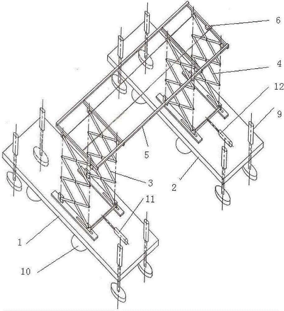
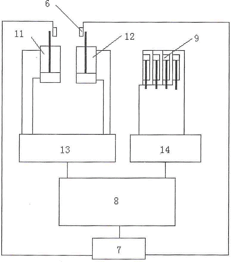
[0012] An in-situ vertical lifting device for a large-scale transformer bell jar, comprising left and right bases 1, 2, and left and right double scissor lifting devices 3, 4 respectively installed on the left and right bases, which are lifted and lifted by left and right pneumatic cylinders, The top of the left and right double scissor lifting devices is equipped with a crossbeam 5, on which a hook for lifting the transformer hanging bell is installed; The control module 7 is connected, and the main frame 8 of the control module is connected with the synchronous control device 13 which controls the synchronous movement of the left and right pneumatic cylinders 11 and 12;

[0013] When working, the host computer of the control system issues instructions, the left and right pneumatic cylinders work, and the left and right pneumatic cylinders push the left and right double scissor lifting devices to drive the beam up, and the beam lifts the transformer bell jar through the hook; ...


PUM


Abstract

The present invention discloses a large transformer bell indoor in-situ vertical lifting apparatus, wherein a left double shear fork lifting device pushed by a left gas cylinder and a right double shear fork lifting device pushed by a right gas cylinder are respectively arranged on a left base and a right base, the top portions of the left double shear fork lifting device and the right double shear fork lifting device are provided with cross beams, the cross beams are provided with lifting hooks for lifting the transformer bell, a displacement sensor for detecting whether the lifting heights of the left double shear fork lifting device and the right double shear fork lifting device are the same is arranged on the cross beams and is connected with a control system, the cross beam comprises a group of left longitudinal rods, a group of right longitudinal rods, a front transverse rod, and a rear transverse rod, the group of the left longitudinal rods and the group of the right longitudinal rods respectively comprise two longitudinal rods, each longitudinal rod is fixedly connected with the top portion of the one shear fork lifting part of the double shear fork lifting device, and the four parallel transverse rods are fixedly connected with the group of the left longitudinal rods and the group of the right longitudinal rods. According to the present invention, the transformer lifting apparatus adopts the double shear fork type gantry structure, wherein the maximum lifting height can achieve 8 m, and the maximum weight lifting can achieve 10 tons.

Description

technical field [0001] The invention relates to a lifting device for a transformer bell jar. Background technique [0002] In the prior art, the lifting of the indoor transformer bell jar generally adopts ordinary lifting facilities, and the building structure needs to be destroyed during the construction to operate, and the skills of the operators are greatly affected, and the working performance is not ideal, which needs further improvement. Contents of the invention [0003] The purpose of the present invention is to provide a kind of reasonable structure, good working performance large-scale transformer bell indoor vertical hoisting device on the spot. [0004] Technical solution of the present invention is: [0005] An in-situ vertical lifting device for a large-scale transformer bell jar, which is characterized in that it includes left and right bases, and left and right double scissor lifting devices are respectively installed on the left and right bases, which are...

Claims


Application Information

Patent Timeline
IPC IPC(8): B66C19/00B66C13/20
CPCB66C13/20B66C19/00B66F7/08B66C2700/01
Inventor 朱富云陈锦翔陈佳妮周建智
Owner STATE GRID CORP OF CHINA
Why Eureka
Try Eureka