Flexible clamp apparatus for automobile assembly parts conveying system

A technology for conveying systems and parts, which is applied in the field of flexible holding devices for automobile assembly parts conveying systems, can solve the problem of inability to meet the lifting requirements of various auto parts, the inability to realize the lifting requirements of various parts, intelligence and Poor flexibility and other problems, to save the time of changing the holding device, good effect, fast and accurate positioning effect

Active Publication Date: 2017-02-22
CHONGQING UNIV
View PDF8 Cites 7 Cited by
  • Summary
  • Abstract
  • Description
  • Claims
  • Application Information

AI Technical Summary

Problems solved by technology

The car assembly hug is a rigid hug. Although it can meet the transfer requirements of different types of cars with large differences in chassis structure, it can only be lifted for the chassis and frame assembly of the car. It is very intelligent and flexible. Poor, unable to meet the lifting requirements for various parts
[0004] In the same way, the Chinese patent with the publication number CN201284375 discloses a multi-vehicle collinear hugging device for automobile body aerial machine transportation lines, including a hugging hanger and a hugging base, the lower part of the hugging hanger is fixedly connected to the hugging base, and The base of the tool is fixed with a low fulcrum, the low fulcrum is composed of a spring locking mechanism, a handle, and an adjusting bolt. The upper part of the spring locking mechanism is equipped with an eccentric ejector pin as a fulcrum for connecting the car floor, and the lower part is equipped with a handle. The spring locking mechanism The bottom plate is installed on the base of the cradle through adjusting bolts; the base of the cradle is also equipped with a high fulcrum, which includes a guide assembly, a spring locking mechanism, a handle, a positioning pin, and a fulcrum adjustment bolt, and the guide assembly is installed through the fulcrum adjustment bolt On the base of the cradle, the height of the guide assembly is lower than the height of the low fulcrum. Several bolts and at least two positioning holes are arranged on the upper surface of the guide assembly; The fulcrum of the bottom plate, the lower part is equipped with a handle, the bottom plate of the spring locking mechanism has several round and bar-shaped through-slots connected with each other, the round-strip-shaped through-slots correspond to the bolts on the guide assembly, and the spring locking mechanism There are also at least two pin holes on the base plate, which correspond to the positioning holes on the guide assembly, and the positioning pins can be inserted into the pin holes on the base plate of the spring locking mechanism and the positioning holes on the guide assembly to affix the two into a Overall, the structure of the device is relatively complicated, and there are too many small parts, which is inconvenient to disassemble and maintain. It is a rigid holding device.
The multi-vehicle co-linear holding device of the car body aerial machine transportation line meets the hoisting requirements of different car models by setting low and high fulcrums, but it is poor in intelligence and flexibility, and cannot meet the hoisting requirements of various auto parts.

Method used


Image

  • Flexible clamp apparatus for automobile assembly parts conveying system
  • Flexible clamp apparatus for automobile assembly parts conveying system
  • Flexible clamp apparatus for automobile assembly parts conveying system

Examples


Embodiment Construction

[0038] The present invention will be further described below in conjunction with the accompanying drawings and specific embodiments, so that those skilled in the art can better understand the present invention and implement it, but the examples given are not intended to limit the present invention.

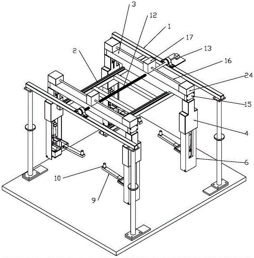
[0039] Such as figure 2 As shown, it is a structural schematic diagram of an embodiment of the flexible holding device of the automobile assembly parts delivery system of the present invention. The flexible holding device of the automobile assembly parts delivery system in this embodiment includes two load beams 1 parallel to each other, and a slide rail 2 perpendicular to the load beam 1 is arranged between the two load beams 1. There are at least two embracing units, and a spacing adjustment mechanism for respectively adjusting the distance between two adjacent embracing units is provided between the two load beams 1 .

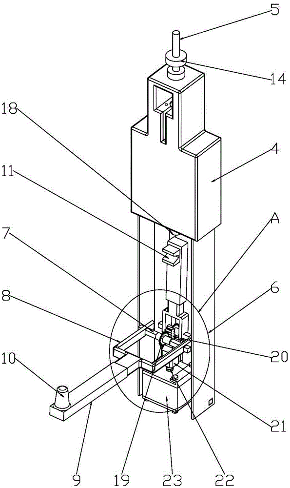
[0040] The holding unit includes a support frame 3 which...


PUM


Abstract

The invention discloses a flexible clamp apparatus for an automobile assembly parts conveying system, comprising two bearing beams parallel to each other; a slide rail is provided between the two bearing beams, at least two clamp units are disposed on the slide rail, a spacing adjustment is arranged between the two bearing beams, each clamp unit comprises a support frame slidably and fitly mounted on the slide rail, two ends of the support frame are provided with clamp mechanisms respectively, each clamp mechanism comprises a connecting sleeve, the upper end of each connecting sleeve is provided with a connecting shaft that is rotationally fitly connected with the corresponding support frame, a rotational drive mechanism is arranged on each support frame, the lower end of each connecting sleeve is provided with a clamp support that is provided with a switching support mechanism, each switching support mechanism comprises two rotary shafts arranged horizontally and parallel to each other with the two rotary shafts being rotationally fitly mounted to the corresponding clamp supports respectively, a connecting fork is connected to each rotary shaft, a support rod is releasably mounted on each connecting fork, each support rod is provided with a positioning pin or a V-shaped block, and each clamp support is provided with a switching drive mechanism.

Description

technical field [0001] The invention belongs to the field of hugging technology, in particular to a flexible hugging device for an automobile assembly parts delivery system. Background technique [0002] Such as figure 1 As shown, it is a structural schematic diagram of an existing rigid conveying system for automobile assembly. The conveying system for automobile assembly generally includes a conveying track. Correspondingly, there are pre-stop points, and the holding device is slidably fitted and installed under the conveying track. The working process is as follows: the holding device stays at the pre-stop point for feeding, and moves into the top of the feeding point after receiving the signal that the front car group moves out. Then the spreader lowers, and the holding device grabs the parts; after the parts are sensed in place, the holding device clamps the parts, and then the spreader rises, and after rising in place, the spreader moves out of the loading point; move...

Claims


Application Information

Patent Timeline
Patent Type & Authority Applications(China)
IPC IPC(8): B62D65/18
CPCB62D65/18
Inventor 王彦凯王时龙杨波唐倩
Owner CHONGQING UNIV
Why Eureka
Try Eureka