Driving pipe mechanism for mounting rotary shafts

A driving tube and installation technology, applied in couplings, mechanical equipment, rigid shaft couplings, etc., can solve the problems of inconvenient driving and poor driving stability.

Inactive Publication Date: 2015-08-19
胡和萍
View PDF6 Cites 5 Cited by
  • Summary
  • Abstract
  • Description
  • Claims
  • Application Information

AI Technical Summary

Problems solved by technology

Existing drive shafts such as rotary shafts are in

Method used


Image

  • Driving pipe mechanism for mounting rotary shafts
  • Driving pipe mechanism for mounting rotary shafts

Examples


Embodiment Construction

[0012] The preferred embodiments of the present invention will be described in detail below in conjunction with the accompanying drawings, so that the advantages and features of the present invention can be more easily understood by those skilled in the art, so as to define the protection scope of the present invention more clearly.

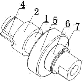
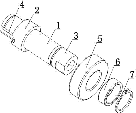
[0013] Such as figure 1 and figure 2 As shown, a drive tube mechanism for installing a rotating shaft includes a drive tube 1, the outer surface of the drive tube 1 is covered with a limit ring 2, one end of the drive tube 1 is provided with a drive end 3, and the side wall of the other end of the drive tube 1 There is a card slot 4, the drive tube 1 is set with a plane bearing 5 and a buckle 6; the drive tube 1 is set with a fastening ring 7, and the fastening ring 7 is buckled on the outside of the buckle 6, and the drive tube 1 and the limit ring 2 are One structure.

[0014] The driving tube mechanism for installing the rotating shaft of t...


PUM


Abstract

The invention discloses a driving pipe mechanism for mounting rotary shafts. The driving pipe mechanism comprises a driving pipe. A limiting ring sleeves the outer surface of the driving pipe, a driving end is arranged at one end of the driving pipe, a clamp groove is formed in a side wall of the other end of the driving pipe, and a plane bearing and a retaining ring sleeve the driving pipe. The driving pipe mechanism has the advantages that the rotary shafts can be conveniently inserted in one end of the driving pipe, the other end of the driving pipe can be conveniently connected with a driving motor, accordingly, rotation of the driving pipe can be conveniently controlled, and rotation of the rotary shafts can be controlled.

Description

technical field [0001] The invention relates to a driving tube mechanism, in particular to a driving tube mechanism for installing a rotating shaft. Background technique [0002] The driving shaft is a kind of working device of the loader, which is a device that can push the smoothness of the loader so that the driving wheels can rotate at different angular speeds. Existing driving shafts such as rotating shafts are inconvenient to drive and have poor driving stability. Contents of the invention [0003] The present invention mainly solves the technical problems existing in the prior art, thereby providing a convenient plug-in rotation shaft through one end of the drive tube, and convenient connection with the drive motor through the other end of the drive tube, so as to facilitate the rotation control of the drive tube. A drive tube mechanism is attached to the rotating shaft to control the rotation of the rotating shaft. [0004] Above-mentioned technical problem of t...

Claims


Application Information

Patent Timeline
IPC IPC(8): F16D1/02
Inventor 胡和萍
Owner 胡和萍
Why Eureka
Try Eureka