A calibration method and calibration system for improving yto preset accuracy

A calibration method and accuracy technology, applied in the field of signal processing, can solve the problems of frequent changes in the loss-of-lock judgment level, inability to accurately judge the loop state, unstable output of the comparison circuit, etc., so as to reduce the workload of manual debugging and simplify the test. Connection and calibration costs, the effect of high calibration efficiency

Active Publication Date: 2018-12-04
THE 41ST INST OF CHINA ELECTRONICS TECH GRP
View PDF7 Cites 0 Cited by
  • Summary
  • Abstract
  • Description
  • Claims
  • Application Information

AI Technical Summary

Problems solved by technology

The advantage of this method is that no external test equipment is needed, and automatic calibration software can be used to realize automatic calibration, which reduces the workload of manual debugging and improves calibration efficiency; the disadvantage is that the preset value needs to be adjusted gradually during the calibration process, and the step is too The large deviation of the calibration value will lead to unsatisfactory calibration effect; too small step will cause the calibration process to be too slow and the calibration efficiency to be low
In addition, when the error voltage is basically equal to the reference voltage of the comparator, the output of the comparator circuit will appear unstable, and the lock-out judgment level changes frequently, making it impossible to accurately judge the state of the loop. An exception should be made for this phenomenon during the calibration process. processing, repeated detection and elimination of the phenomenon

Method used


Image

  • A calibration method and calibration system for improving yto preset accuracy
  • A calibration method and calibration system for improving yto preset accuracy
  • A calibration method and calibration system for improving yto preset accuracy

Examples


Embodiment 1

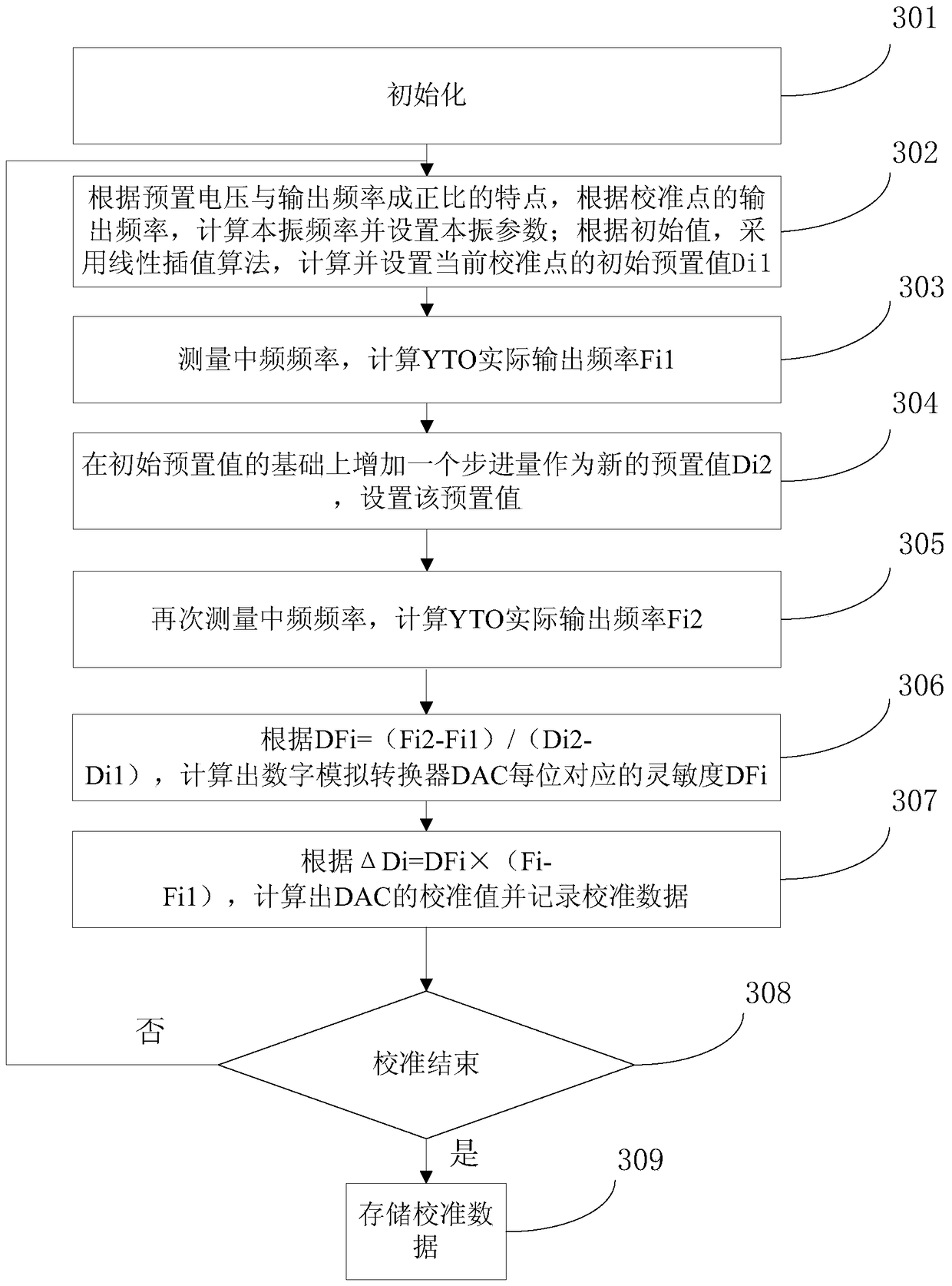
[0050] image 3 It is a flowchart of a calibration method for improving YTO preset accuracy in the present invention, as shown in the figure, including:

[0051] Step 302, according to the characteristic that the preset voltage is proportional to the output frequency, calculate the local oscillator frequency and set the local oscillator parameters according to the output frequency of the calibration point; according to the initial value, use a linear interpolation algorithm to calculate and set the initial preset value of the current calibration point set value Di1;

[0052] Step 303, measure the frequency of the intermediate frequency, and calculate the actual output frequency Fi1 of YTO;

[0053] Step 304, adding a step amount on the basis of the initial preset value as a new preset value Di2, and setting the preset value;

[0054] Step 305, measure the intermediate frequency frequency again, and calculate the actual output frequency Fi2 of YTO;

[0055] Step 306, accordi...

Embodiment 2

[0072] Figure 4 It is a structural diagram of a calibration system for improving YTO preset accuracy provided by the present invention.

[0073] As shown in the figure, the system includes a frequency measurement module, which is set in the programmable logic module and used to measure the intermediate frequency.

[0074] Optionally, the frequency measurement module uses multi-period synchronous measurement for the intermediate frequency.

[0075] Figure 5 It is the timing diagram of continuous wave signal measurement; as shown in the figure, assuming that the preset gate time is Tp, Tp generates the actual gate time T synchronized with the intermediate frequency signal (fX) through the synchronous circuit. The counter counts the measured intermediate frequency and the internal clock signal (f0) within T time respectively, and the counting values ​​are respectively NA=fX×T and NB=f0×T, so fX=NA / NB×f0, the obtained Measure the frequency value. This measurement method elim...


PUM


Abstract

The invention relates to the technical field of signal processing, in particular to a calibration method and a calibration system for improving the accuracy of YTO presets; by adding a frequency measurement module to the programmable logic unit, the frequency is measured for the intermediate frequency, and then the actual output frequency of the YTO is calculated The error with the set frequency does not require external test instruments and equipment, which simplifies the test connection and calibration costs; only two manual calibration points are required, and a set of empirical values ​​can be used as the initial value of all loops, reducing manual debugging Workload: For devices that are not sensitive to frequency switching time, the invention can realize instant calibration, which is more suitable for the working conditions at that time, and can avoid the influence of temperature drift and aging on the loop lock, and the loop work is more stable and reliable.

Description

technical field [0001] The invention relates to the technical field of signal processing, in particular to a calibration method and a calibration system for improving YTO preset accuracy. Background technique [0002] Due to the advantages of the yttrium iron garnet tuned oscillator YTO in frequency coverage, tuning linearity, and spectral purity, broadband microwave synthesis signal generators widely use YTO as the core microwave oscillator. YTO is a solid-state microwave oscillator with yttrium iron garnet YIG balls as resonators and microwave transistors as active devices. Its output frequency has a good linear relationship with the internal tuning magnetic field. The high-performance YTO internal tuning magnetic field is generated by two parts, the main coil and the secondary coil. The former has a large inductive reactance, slow tuning but high tuning sensitivity, wide tuning range, and good high-frequency interference suppression; the latter has a small inductive react...

Claims


Application Information

Patent Timeline
Patent Type & Authority Patents(China)
IPC IPC(8): G01R23/02
Inventor 杜念文朱伟毛黎明任水生凌伟刘娜
Owner THE 41ST INST OF CHINA ELECTRONICS TECH GRP
Why Eureka
Try Eureka