
Passive atomic frequency standard

An atomic frequency standard, passive technology, applied in the direction of automatic power control, electrical components, etc., can solve the problems of atomic spectral line distortion, uneven applied magnetic field, and no real reflection of the center frequency value.

Active Publication Date: 2016-07-06
JIANGHAN UNIVERSITY
View PDF4 Cites 0 Cited by
  • Summary
  • Abstract
  • Description
  • Claims
  • Application Information

AI Technical Summary

Problems solved by technology

[0005] Since the physical module may be affected by electronic circuits (voltage-controlled crystal oscillator, microwave generation module, servo module, etc.) It is the superposition of each part of the atomic spectral lines. The shape of the atomic spectral lines reflects the distribution of the magnetic field in the microwave cavity. In this case, the atomic spectral lines will cause the actual atomic spectral lines due to the uneven and asymmetric applied magnetic field. Distortion occurs. In the case of atomic spectral line distortion, when f1 and f2 are on both sides of fo, the two detected voltages V1 and V2 are not equal, that is, in the prior art, it is considered that the alignment When the atomic transition center frequency fo, that is, when V1=V2, does not actually reflect the center frequency value
Therefore, the existing technology cannot accurately lock the center frequency of the atomic transition

Method used


Image

  • Passive atomic frequency standard
  • Passive atomic frequency standard

Examples


Embodiment Construction

[0026] In order to make the object, technical solution and advantages of the present invention clearer, the implementation manner of the present invention will be further described in detail below in conjunction with the accompanying drawings.

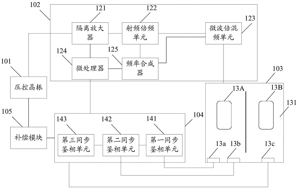
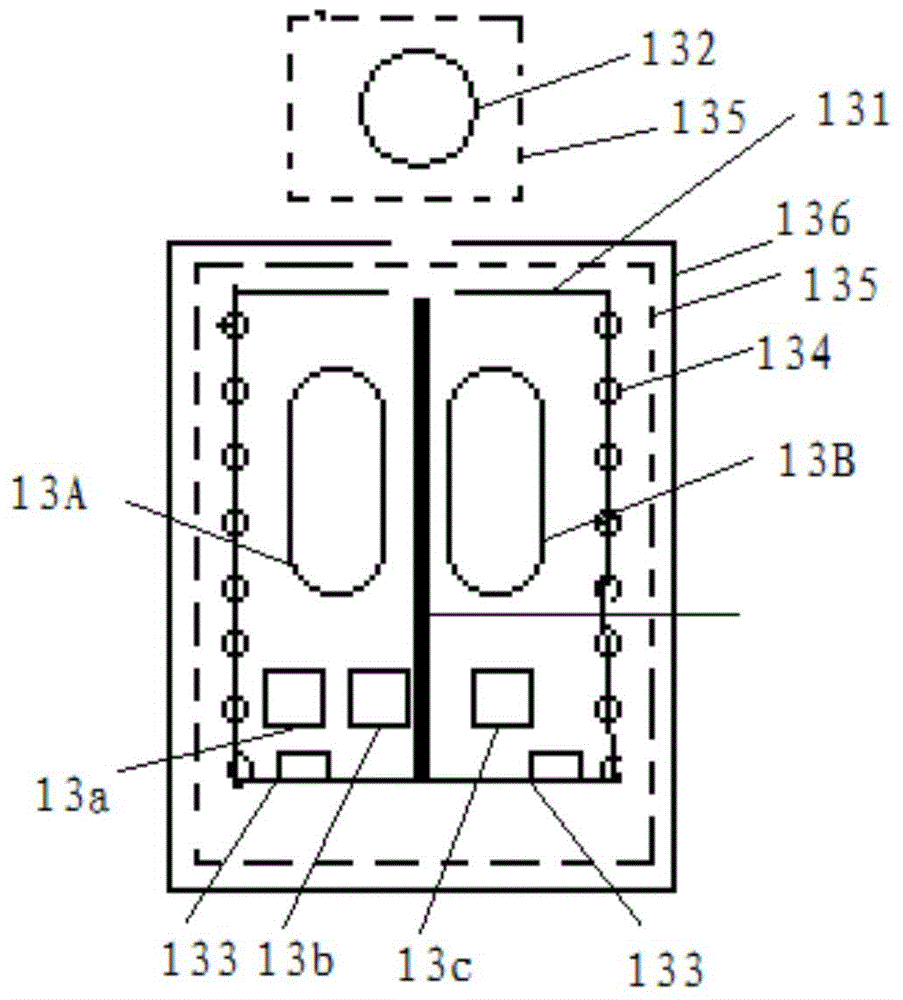
[0027] figure 1 It is a structural schematic diagram of a passive atomic frequency standard (hereinafter referred to as an atomic frequency standard) provided by an embodiment of the present invention, see figure 1 , the atomic frequency standard includes: a voltage-controlled crystal oscillator 101, a microwave generation module 102, a physical module 103, a phase detector module 104 and a compensation module 105, the physical module 103 includes a microwave cavity 131, and the first cavity bubble 13A and the first cavity bubble 13A are arranged side by side in the microwave cavity 131 The second cavity bubble 13B, the tail of the microwave cavity 131 is also provided with a first photocell 13a, a second photocell 13b and a third phot...


PUM


Abstract

The invention discloses a passive atomic frequency standard, and belongs to the field of atomic frequency standards. The passive atomic frequency standard comprises a voltage control crystal oscillator, a microwave generation module, a physical module, a phase demodulation module and a compensation module, wherein the microwave generation module is electrically connected to the voltage control crystal oscillator, the physical module and the phase demodulation module; the phase demodulation module is also electrically connected to the physical module and the compensation module; the compensation module is also electrically connected to the voltage control crystal oscillator; the physical module comprises a microwave cavity; a first cavity cell and a second cavity cell are arranged in the microwave cavity in parallel; a first photocell, a second photocell and a third photocell are further arranged at the tail of the microwave cavity; the first photocell and the second photocell are arranged in parallel; the first photocell and the second photocell are symmetrical relative to the middle axis of the first cavity cell; and the third photocell is arranged at the middle axis of the second cavity cell.

Description

technical field [0001] The invention relates to the field of atomic frequency standards, in particular to a passive atomic frequency standard. Background technique [0002] In order to obtain a relatively stable time frequency in nature, people apply a weak magnetic field to atoms such as rubidium, cesium, hydrogen, etc., to change the atomic energy level from the ground state to the excited state, and use the ground state hyperfine structure 0-0 The transition center frequency is used as the reference time frequency value. [0003] In the atomic frequency standard, the detection signal output by the voltage-controlled crystal oscillator is processed by the microwave generation module to obtain the microwave inquiry signal. The microwave inquiry signal includes two sidebands f1 and f2; For the frequency discrimination signals V1 and V2, if V1 is equal to V2, it means that f1 and f2 are exactly on the left and right sides of the central frequency fo of the atomic spectral li...

Claims


Application Information

Patent Timeline
Patent Type & Authority Applications(China)
IPC IPC(8): H03L7/26
CPCH03L7/26
Inventor 张霞
Owner JIANGHAN UNIVERSITY
Learn More