Micro projection device
A micro-projection and equipment technology, applied in the field of projection display, can solve the problems of optical designers unable to adjust the design and debugging.
- Summary
- Abstract
- Description
- Claims
- Application Information
AI Technical Summary
Problems solved by technology
Method used
Image
Examples
Embodiment 1
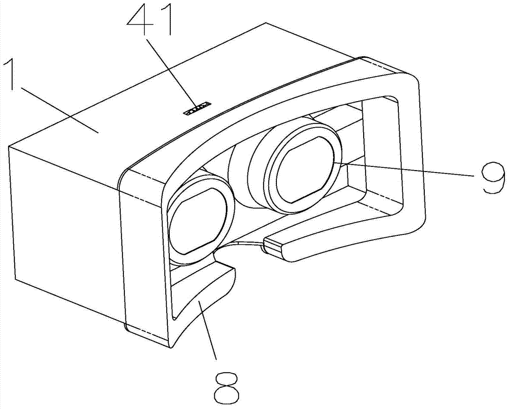
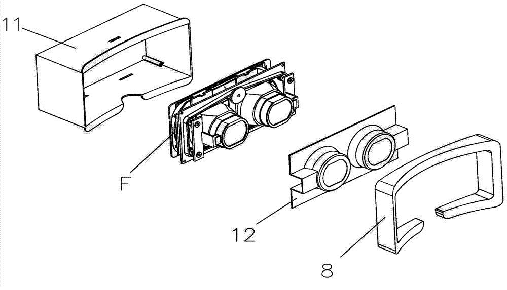
[0060] The above-mentioned lens module 3 includes a module lens barrel 3a and a lens 3b installed in the module lens barrel 3a. The lens module 3 can adopt the most basic optical structure, that is, the lens module 3 is only provided with one lens 3b, and the lens module 3 The lens 3b is a convex lens. However, in order to achieve optical designs such as eliminating chromatic aberration, eliminating image distortion, and magnifying the viewing angle, the lens module 3 will include at least two lenses 3b, and these lenses 3b can be installed in the module lens barrel 3a designed as a whole. They can be grouped and arranged in separate lens barrels according to needs, so as to realize more precise and complex optical adjustment design.
[0061] For the implementation structure in which these lenses 3b are grouped and arranged in different separate lens barrels according to needs, the above-mentioned lens module 3 may include at least two lens assemblies 31 that are sequentially ...
Embodiment 2
[0064] In order to make every two adjacent lens assemblies 31 produce relative movement when the diopter is adjusted by the adjustment dial 41, and to make the display module 2 and the adjacent lens assemblies 31 produce relative movement when the diopter is adjusted by the adjustment dial 41. The movement can make two adjacent lens adjustment threaded sections 453 different, and make the display adjustment threaded section 452 different from the lens adjustment threaded section 452 adjacent to the display adjustment threaded section 452. The difference here can be reflected in, for example, pitch, Any one or any number of thread design elements such as rotation direction, thread lead angle, number of threads, and lead are different. In addition, each thread segment can adopt a regular thread, and can also be designed as an irregular thread as required.
[0065] On this basis, the present invention provides an optical adjustment structure in combination with the above-mentione...
Embodiment 3
[0067] The number of the above-mentioned adjustment shafts 45 is preferably such that the push plate 6 is threadedly connected with the lens adjustment threaded sections 453 of at least two adjustment shafts 45, so as to achieve the purpose of the push plate 6 being installed in the outer cover 1 to limit the rotation relative to the mounting plate 42, and The display module 2 is threadedly connected with the display adjustment threaded sections 452 of at least two adjustment shafts 45, so that the display module 2 is installed in the housing 1 in a manner that restricts rotation relative to the mounting plate 4. In this way, the display module 2 and The push plate 6 does not need to use an additional guide post guide structure or a slider slide rail structure to assist in realizing the anti-rotation design. Taking the module 2 as an example, the guide column guide structure or the slider slide rail structure can be arranged between the display module 2 and the mounting plate 4...
PUM
 Abstract
Description
Claims
Application Information
 - R&D
- Intellectual Property
- Life Sciences
- Materials
- Tech Scout
- Unparalleled Data Quality
- Higher Quality Content
- 60% Fewer Hallucinations
Browse by: Latest US Patents, China's latest patents, Technical Efficacy Thesaurus, Application Domain, Technology Topic, Popular Technical Reports.
© 2025 PatSnap. All rights reserved.Legal|Privacy policy|Modern Slavery Act Transparency Statement|Sitemap|About US| Contact US: help@patsnap.com


