Assembly equipment and assembly method of fluid ejector

A fluid injector and assembly equipment technology, applied in welding equipment, laser welding equipment, metal processing equipment, etc., can solve the problem of injector responsiveness, excessive travel of movable parts, affecting injector performance and other problems, to achieve the effect of improving assembly efficiency and quality, relaxing the tolerance range of concentricity error, and avoiding inconsistent adjustment values.

Active Publication Date: 2015-08-26
CHINA FAW LIMITED WUXI FUEL INJECTIONEQUIP RES INST +2
View PDF7 Cites 14 Cited by
  • Summary
  • Abstract
  • Description
  • Claims
  • Application Information

AI Technical Summary

Problems solved by technology

[0006] In this assembly method, the operation of adjusting the stroke of the movable part is cumbersome and the stroke error is relatively large, which may easily cause the stroke of the movable part to be too large or too small, thereby affecting the metering accuracy of the injector flow rate and the responsiveness of the injector, and ultimately affecting The performance of the injector

Method used


Image

  • Assembly equipment and assembly method of fluid ejector
  • Assembly equipment and assembly method of fluid ejector
  • Assembly equipment and assembly method of fluid ejector

Examples


Embodiment Construction

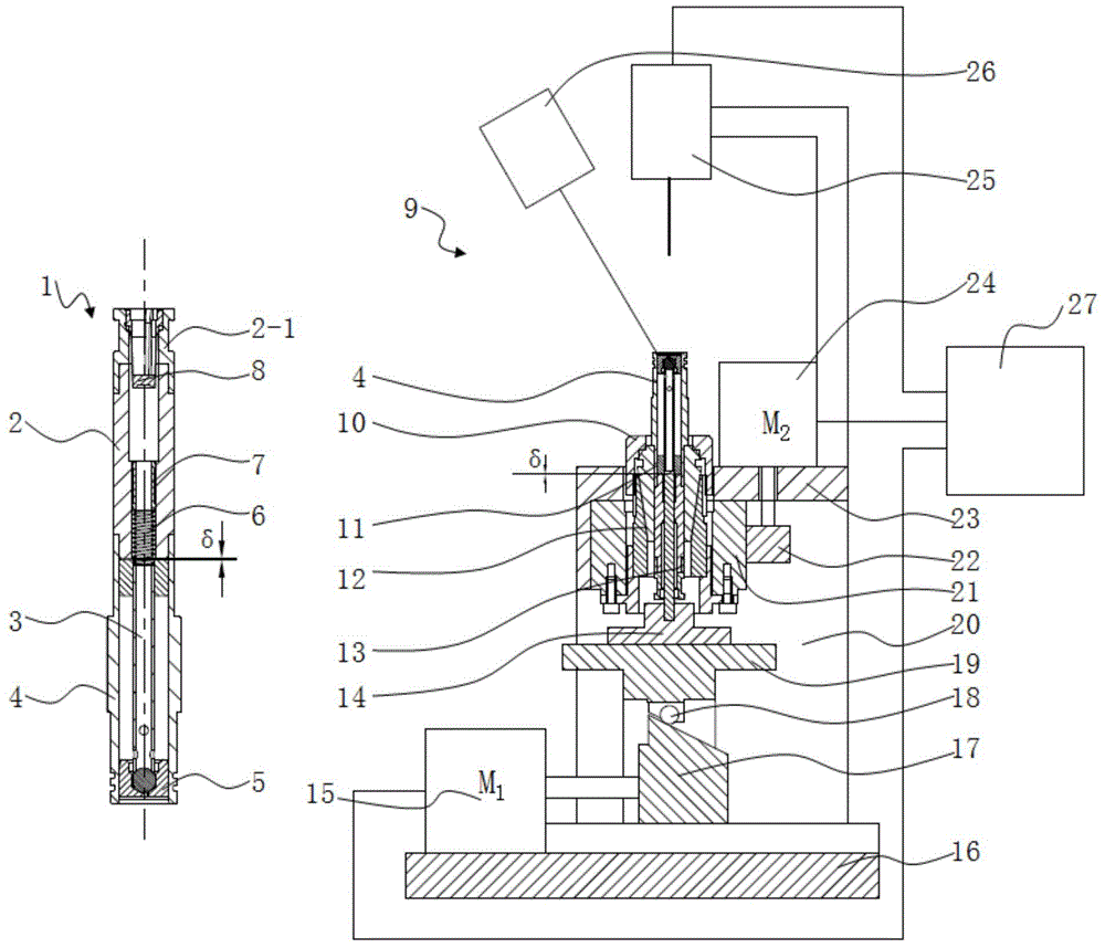
[0036] Such as figure 1 , 4 , The fluid injector shown in 5, 6, and 7 includes components such as a fixed iron core 2, a movable part 3, a valve sleeve 4, a valve seat 5, a spring 6, an elastic cylindrical pin 7, and a filter 8.

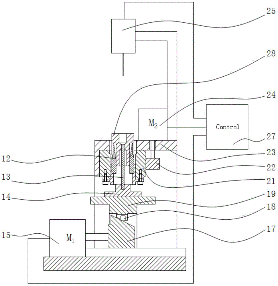
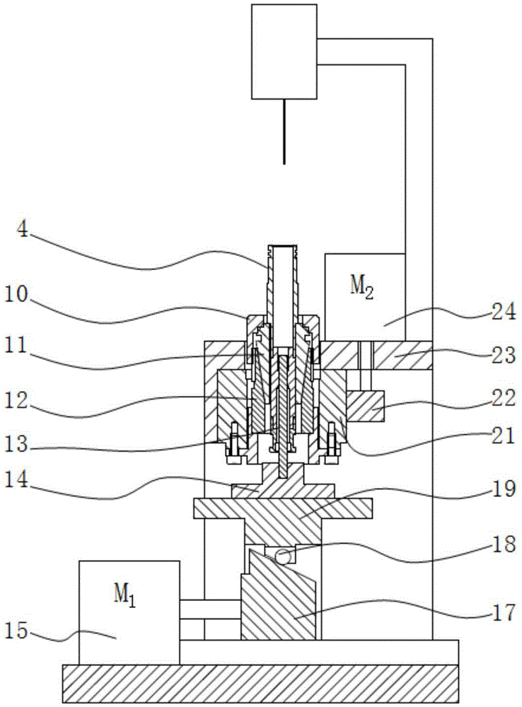
[0037] Such as figure 1 , 2 , 3, 5, and 6 show the assembly equipment (9), including the ejector rod 13, the ejector rod seat 14, the lifting motor 15, the lifting displacement platform 19, the rotating motor 24, the displacement sensor 25, the displacement controller 27, etc., the described Lifting motor 15 drives the stroke of lifting displacement platform 19 to be greater than the distance between the lower end surface of movable part 3 and the top surface of push rod 13 when the zero point of displacement sensor 25 is set and the sum of the set lift of movable part 3.

[0038] The position of the top surface of the push rod 13 is lower than the lower end surface of the movable part 3 before the zero position of the displacement sensor 25 is se...


PUM


Abstract

The invention discloses assembly equipment of a fluid ejector. The assembly equipment comprises a rack, a lifting mechanism, a clamping and rotating mechanism, a displacement sensor, a displacement controller and welding equipment, wherein the lifting mechanism is arranged at the lower part of the rack; the clamping and rotating mechanism is arranged above the lifting mechanism; the displacement sensor is arranged above the clamping and rotating mechanism; the welding equipment is arranged on one side of the clamping and rotating mechanism. The invention further discloses an assembly method of the fluid ejector. The assembly method comprises the following steps: firstly, pressing the other end, where an ejecting opening is formed, of a valve sleeve in the outer circumference at the top end of the a fixed iron core for welded fixing; secondly, adjusting the lifting range of a movable part through the displacement sensor and the displacement controller, and conducting welded fixing on a valve seat; finally, mounting the other parts. The assembly equipment and the assembly method have the advantages that the lifting range adjustment precision and the lifting range consistency of the movable part of the fluid ejector are obviously improved, so that the flow measurement precision and the responsiveness of the fluid ejector are guaranteed, and the assembly efficiency and quality are greatly improved; meanwhile, the allowable concentricity error ranges of armature and sealing parts can be widened, so that the difficulties of part processing and assembly are reduced.

Description

technical field [0001] The invention relates to an assembly equipment and method for a fluid injector, which is used for assembling movable parts in a valve sleeve, and requires precise control and consistency of the lift of this type of fluid injector, especially electromagnetically driven Fluid metering valve. Background technique [0002] The assembly method of the fluid injector directly affects the assembly quality of the injector. For example, fuel injectors, reducing agent injection metering valves, etc., the key is to assemble the movable parts in the injector so that the lift meets the design accuracy and the consistency of batch assembly, which is very important to ensure the flow performance of the injector. If the lift is too large or too small, it will not only affect the metering accuracy of the injector flow, but also affect the responsiveness of the injector. [0003] The assembly method adopted by the electromagnetic valve injector described in CN200710002...

Claims


Application Information

Patent Timeline
Patent Type & Authority Applications(China)
IPC IPC(8): B23K26/21B23K26/60B23K26/70
CPCB23K26/20
Inventor 朱明健居钰生缪雪龙夏少华姚本容陈霍胡振奇
Owner CHINA FAW LIMITED WUXI FUEL INJECTIONEQUIP RES INST
Why Eureka
Try Eureka