Supercharge Your Innovation With Domain-Expert AI Agents!

C-type hydraulic automatic gate

A hydraulic automatic and gate technology, which is applied in waterway systems, water conservancy projects, water supply devices, etc., can solve problems such as high energy consumption, inconvenient maintenance, and uncontrollable water level in underground storage tanks.

Active Publication Date: 2015-08-26
WUHAN SHENGYU DRAINING SYST
View PDF9 Cites 1 Cited by
  • Summary
  • Abstract
  • Description
  • Claims
  • Application Information

AI Technical Summary

Problems solved by technology

The gate needs to discharge flood according to different water levels, which requires power drive, consumes a lot of energy, and is inconvenient to maintain, and the water level of the underground storage tank cannot be controlled

Method used


Image

  • C-type hydraulic automatic gate
  • C-type hydraulic automatic gate
  • C-type hydraulic automatic gate

Examples


Embodiment Construction

[0024] The present invention will be further described in detail below in conjunction with the accompanying drawings and specific embodiments to facilitate a clear understanding of the present invention, but they do not limit the present invention.

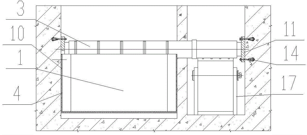
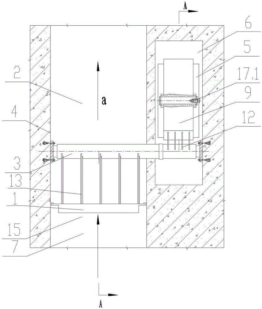
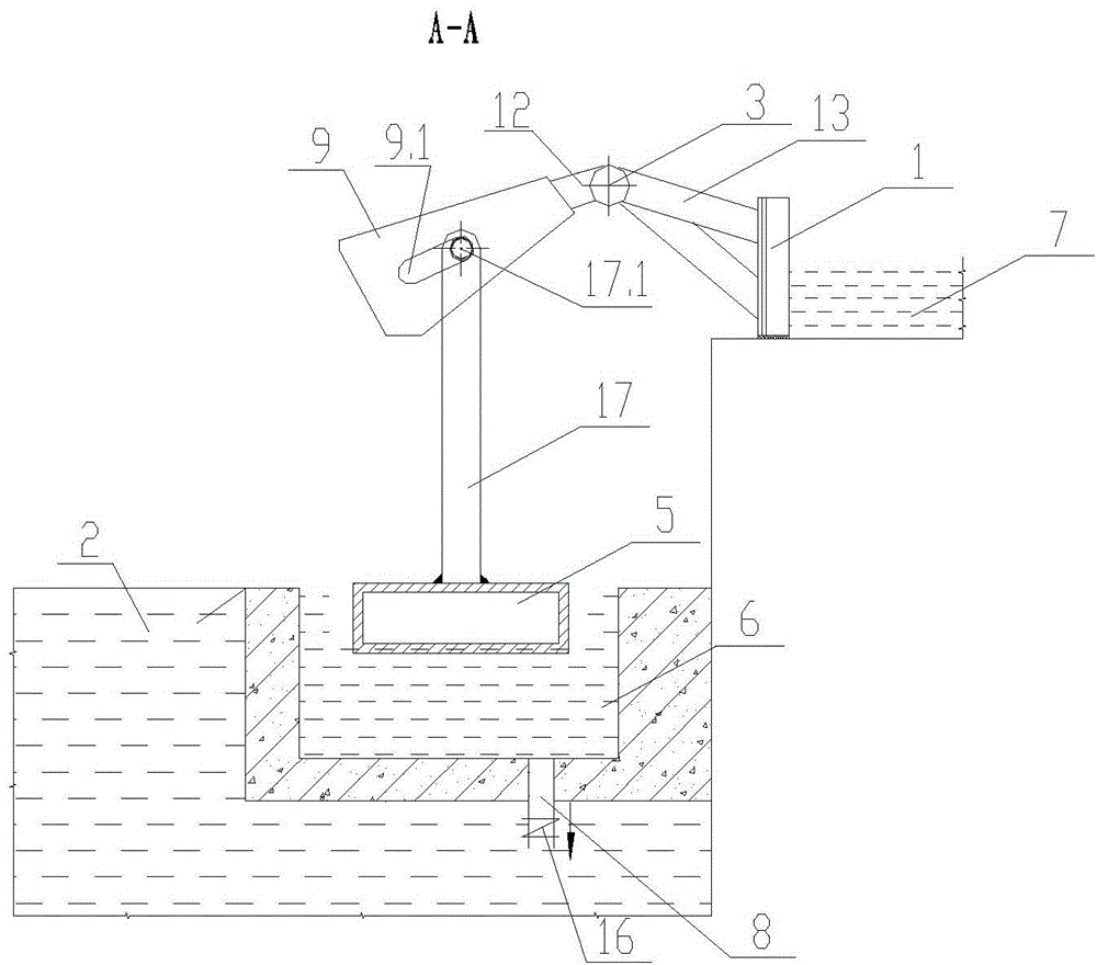
[0025] Such as figure 1 — image 3 As shown, the present invention includes a buffer tank 7 and an underground adjustment storage tank 2 arranged in the flow channel 15, the underground adjustment storage tank 2 is arranged lower than the buffer tank 7, and a gate 1 is arranged between the buffer tank 7 and the underground adjustment storage tank 2 , the two side edges and the bottom edge of the gate 1 are respectively sealed with the flow channel walls 4 on both sides of the flow channel 15, the gate 1 is fixed on one side of the rotating shaft 3, and the two ends of the rotating shaft 3 are respectively hinged on both sides of the flow channel 15 On the flow channel wall 4 of the flow channel 15, the flow channel wall 4 on both...


PUM


Abstract

The invention relates to a C-type hydraulic automatic gate, and belongs to the technical field of drainage system devices. The C-type hydraulic automatic gate comprises a buffering pond and an underground storage pond which are arranged inside a flow pass. The underground storage pond is lower than the buffering pond. A gate body is arranged between the buffering pond and the underground storage pond. The edges of the two sides and the edge of the bottom of the gate body are matched and sealed with the flow pass walls on the two sides of the flow pass respectively. The gate body is fixed to one side of a rotating shaft. The two ends of the rotating shaft are hinged to the flow pass walls on the two sides of the flow pass respectively. The C-type hydraulic automatic gate further comprises a buoyancy tank chamber arranged inside the underground storage pond, wherein water enters the underground storage pond and then enters the buoyancy tank chamber. The other side of the rotating shaft and one end of a connecting rod are fixed. The other end of the connecting rod is hinged to a buoyancy tank which is arranged in the buoyancy tank chamber. A buoyancy tank water outlet hole is formed in the bottom of the buoyancy tank chamber and communicated with the underground storage pond. It is ensured that water in the buffering pond is drained towards the underground storage pond only when the underground storage pond is in the low water level, timely flood discharge is achieved, and meanwhile the gate is turned off when the underground storage pond is in the high water level.

Description

technical field [0001] The invention belongs to the technical field of drainage system equipment, and in particular relates to a C-type hydraulic automatic gate. Background technique [0002] In the system where municipal rainwater or sewage pipe network overflows to natural water bodies (rivers, lakes, etc.), the water level is often controlled by gates. The gate needs to discharge flood according to different water levels, which requires power drive, consumes more energy, is inconvenient to maintain, and the water level of the underground storage tank cannot be controlled. Therefore, how to design a gate structure that is simple in structure, does not consume energy, and can control the water level of the underground storage tank is a problem that is currently faced. Contents of the invention [0003] The object of the present invention is to provide a C-type hydraulic automatic gate aiming at the problems of the prior art. [0004] The technical scheme adopted in the ...

Claims


Application Information

Patent Timeline
IPC IPC(8): E03F7/02E02B7/40
Inventor 李习洪周超
Owner WUHAN SHENGYU DRAINING SYST
Features
  • R&D
  • Intellectual Property
  • Life Sciences
  • Materials
  • Tech Scout
  • Unparalleled Data Quality
  • Higher Quality Content
  • 60% Fewer Hallucinations
Learn More