
OLED pixel drive circuit and OLED display panel

A pixel drive circuit and display panel technology, which is applied to static indicators, instruments, etc., can solve the problems of reducing luminous brightness, increasing the threshold voltage of organic light-emitting diodes, and affecting the life of OLED display panels, so as to prolong life and shorten luminous time Effect

Inactive Publication Date: 2015-09-02
TCL CHINA STAR OPTOELECTRONICS TECH CO LTD
View PDF4 Cites 7 Cited by
  • Summary
  • Abstract
  • Description
  • Claims
  • Application Information

AI Technical Summary

Problems solved by technology

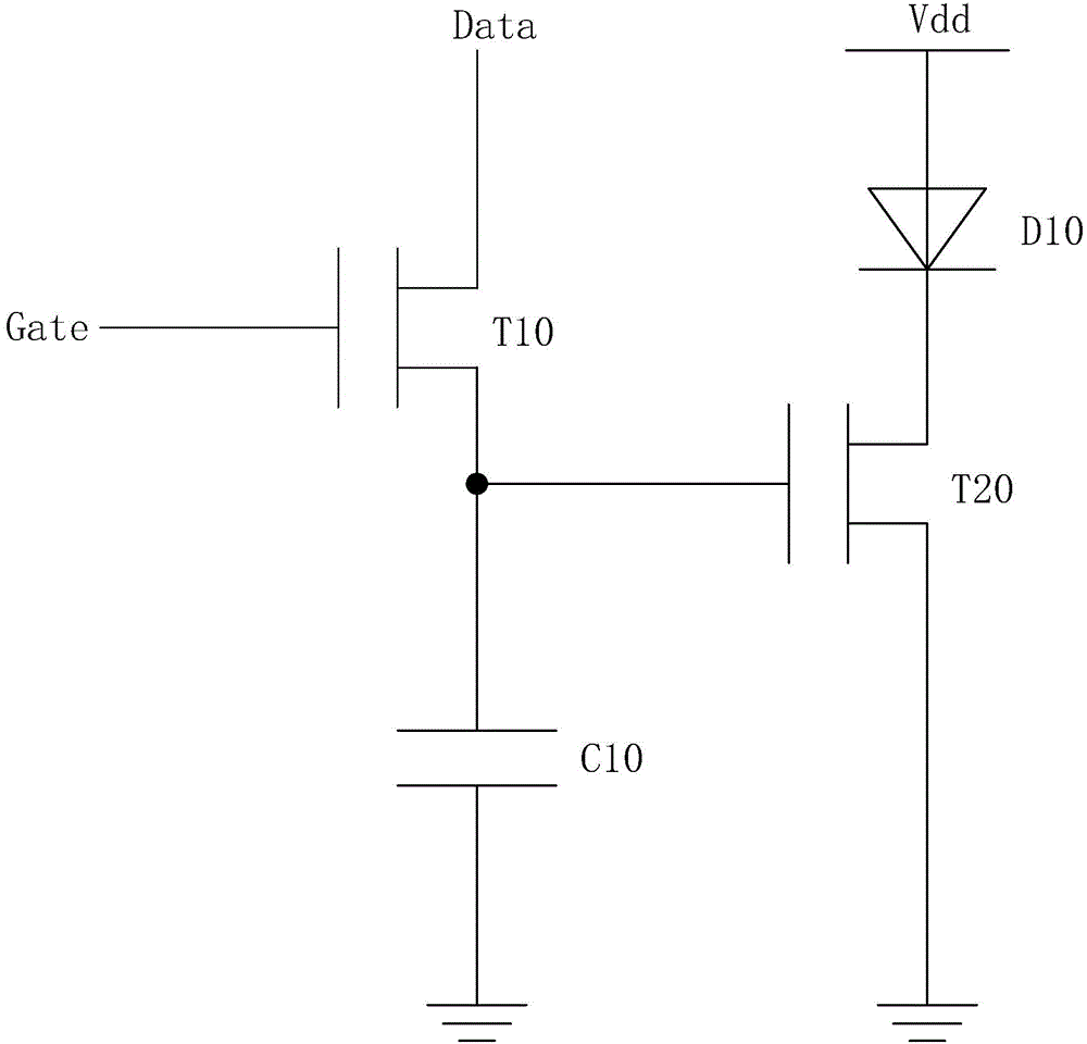
As the usage time of the OLED display panel increases, holes and electrons will accumulate at the interface between the transport layer and the light-emitting layer, forming a built-in electric field inside the organic light-emitting diode, resulting in an increase in the threshold voltage of the organic light-emitting diode and a decrease. Its luminous brightness affects the life of the OLED display panel

Method used


Image

  • OLED pixel drive circuit and OLED display panel
  • OLED pixel drive circuit and OLED display panel
  • OLED pixel drive circuit and OLED display panel

Examples


Embodiment Construction

[0037] In order to further illustrate the technical means adopted by the present invention and its effects, the following describes in detail in conjunction with preferred embodiments of the present invention and accompanying drawings.

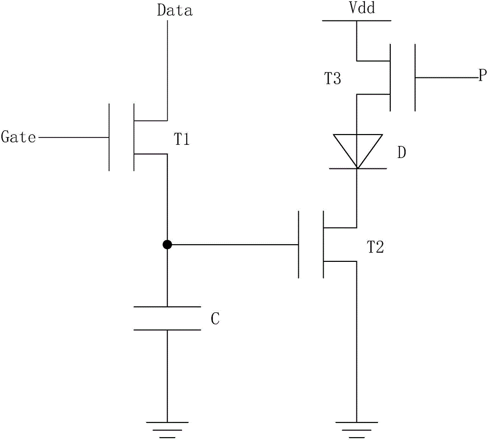
[0038] see figure 1 , The present invention firstly provides an OLED pixel driving circuit, including a first thin film transistor T1, a second thin film transistor T2, a third thin film transistor T3, an organic light emitting diode D, and a capacitor C.

[0039] The gate of the first thin film transistor T1 is electrically connected to the scan line Gate, the drain is electrically connected to the data line Data, and the source is electrically connected to the gate of the second thin film transistor T2 and one end of the capacitor C;

[0040] The gate of the second thin film transistor T2 is electrically connected to the source of the first thin film transistor T1 and one end of the capacitor C, the drain is electrically connected to the cat...


PUM


Abstract

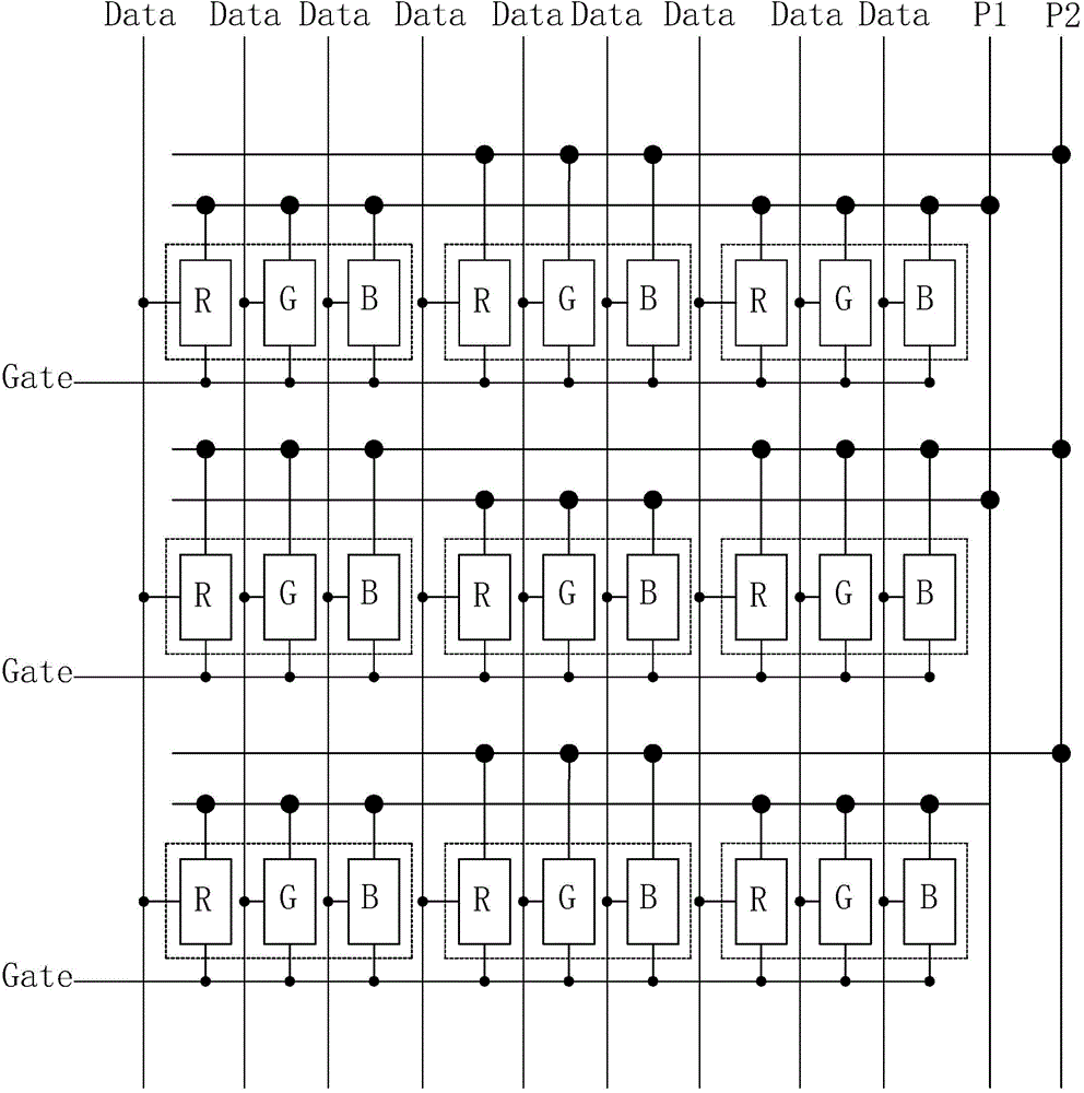
The invention provides an OLED pixel drive circuit and an OLED display panel. The OLED pixel drive circuit is provided with a third thin film transistor (T3) between a DC voltage end (Vdd) and an organic light emitting diode (D), and on-off of the source electrode and the drain electrode of the third thin film transistor (T3) is controlled through control signals (P), so as to conveniently control luminescence time of the OLED. In the OLED display panel, the OLED pixel drive circuit of each sub-pixel is internally provided with the third thin film transistor (T3) between the DC voltage end (Vdd) and the organic light emitting diode (D), and each adjacent two pixels are controlled to be in state that one illuminates and the other does not illuminate in turns in a display process respectively through a first control signal (P1) and a second control signal (P2) whose potentials are opposite, so as to conveniently control the luminescence time of the OLED in each pixel, shorten the luminescence time of the OLED in each pixel, and prolong life of the OLED display panel.

Description

technical field [0001] The invention relates to the field of display technology, in particular to an OLED pixel driving circuit and an OLED display panel. Background technique [0002] Organic light emitting diode (Organic Light Emitting Display, OLED) display device has self-illumination, low driving voltage, high luminous efficiency, short response time, high definition and contrast, nearly 180° viewing angle, wide operating temperature range, and can realize flexible display and With many advantages such as large-area full-color display, it is recognized by the industry as a display device with the most potential for development. [0003] At present, most OLEDs are driven by direct current, which includes: an anode, a hole injection layer on the anode, a hole transport layer on the hole injection layer, a light emitting layer on the hole transport layer, a device An electron transport layer on the light emitting layer, an electron injection layer on the electron transpor...

Claims


Application Information

Patent Timeline
Patent Type & Authority Applications(China)
IPC IPC(8): G09G3/32
CPCG09G3/3233G09G2300/0861G09G2310/0218G09G2310/0262G09G2320/045
Inventor 付舰航
Owner TCL CHINA STAR OPTOELECTRONICS TECH CO LTD
Learn More