Networking method of network
A network and networking technology, applied in the field of network networking, can solve the problems of exhaustion, shortened network life, unbalanced power consumption of nodes, etc., and achieve the effect of low probability of communication conflict
- Summary
- Abstract
- Description
- Claims
- Application Information
AI Technical Summary
Benefits of technology
Problems solved by technology
Method used
Image
Examples
Embodiment 1
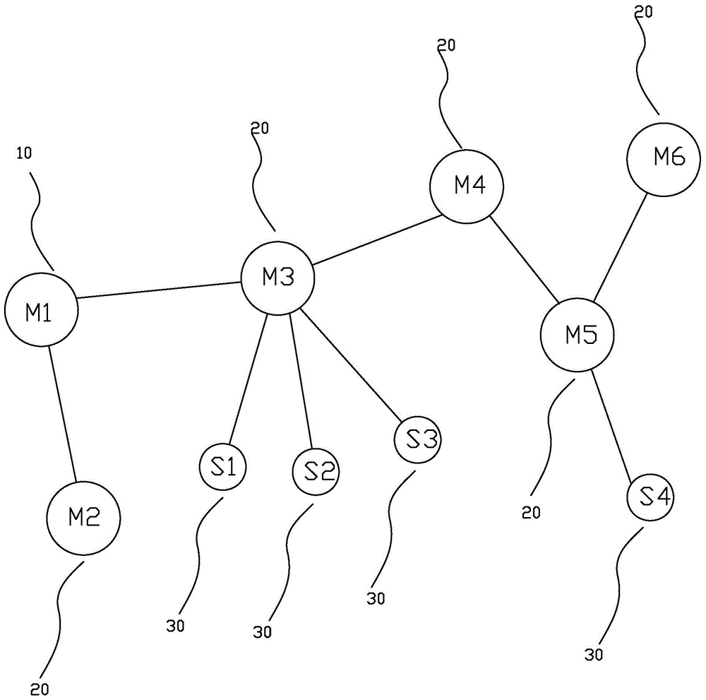
[0051] see figure 1 As shown, a network networking method of the present invention includes: a network networking method, the network includes two logical nodes, a gateway node 10 and a dual-mode node 20;
[0052]The gateway node 10 establishes a direct connection or an indirect connection with the dual-mode node 20 in the network; the two logical nodes in the network use a periodically repeated, unified time frame to perform time-division communication.
Embodiment 2
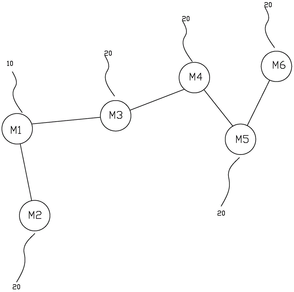
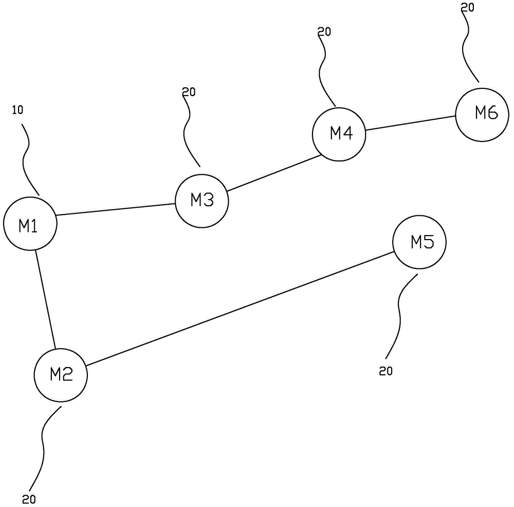
[0054] see Figure 2A with Figure 2B As shown, the gateway node 10 balances the number of connections of different dual-mode nodes 20 under the premise of ensuring that the link signal strength between nodes satisfies one or more service quality indicators, so that the nodes in the network will not be concentrated on a specific few A dual-mode node 20 establishes a connection.
[0055] If the number of connections of each node in a network is not balanced, the number of subordinate connections between some nodes is significantly unbalanced, see Figure 2A As shown, the dual-mode node M3 has three subordinate connections dual-mode node M4, dual-mode node M5, and dual-mode node M6, while the dual-mode node M2 has zero subordinate connections; such a connection mode affects the uninterrupted operation of the entire network Life cycle; balanced by node connections, see Figure 2B As shown, the dual-mode node M3 has two lower-level connections to the dual-mode node M4 and dua...
Embodiment 3
[0057] See 3 to Figure 5 As shown, the gateway node 10 generates a dual-mode node traffic scheduling diagram according to the network topology and transmits it to the dual-mode node 20 in the network; the dual-mode node 20 determines its own traffic scheduling diagram according to the received dual-mode node traffic Wake-up moment; wherein the dual-mode node connected with one or more multi-point access slave nodes 30 generates a multi-point access slave node traffic scheduling graph and transmits it to one or more multi-point access slave nodes 30 connected thereto; The one or more multi-point access slave nodes 30 determine their own wake-up time according to the received multi-point access slave node traffic scheduling graph.
[0058] Further, the dual-mode node traffic scheduling graph includes a channel dimension;
[0059] The dual-mode node 20 determines its own data transmission channel according to the dual-mode node traffic scheduling graph.
[0060] Furthermore, t...
PUM
 Abstract
Description
Claims
Application Information
 - R&D
- Intellectual Property
- Life Sciences
- Materials
- Tech Scout
- Unparalleled Data Quality
- Higher Quality Content
- 60% Fewer Hallucinations
Browse by: Latest US Patents, China's latest patents, Technical Efficacy Thesaurus, Application Domain, Technology Topic, Popular Technical Reports.
© 2025 PatSnap. All rights reserved.Legal|Privacy policy|Modern Slavery Act Transparency Statement|Sitemap|About US| Contact US: help@patsnap.com


