Continuous beam type anti-floating structure of shield tunnel

A shield tunnel and beam-type technology, which is applied in tunnels, infrastructure engineering, protection devices, etc., can solve the problems of small buoyancy resistance, increased tunnel pressure, and high cost, so as to improve the buoyancy resistance, good buoyancy resistance, The effect of reducing the amount of work

Active Publication Date: 2015-09-09
CHINA RAILWAY SIYUAN SURVEY & DESIGN GRP
View PDF9 Cites 7 Cited by
  • Summary
  • Abstract
  • Description
  • Claims
  • Application Information

AI Technical Summary

Problems solved by technology

[0012] (1) The ground is heavily loaded and ballasted, and this anti-floating measure is generally difficult to achieve due to ground conditions during long-term operation;
[0013] (2) Use the useless space in the shield tunnel to fill concrete or other counterweight materials to increase the self-weight of the tunnel, but because the internal space of the shield tunnel is limited, the increased counterweight in the tunnel may not be able to completely overcome the buoyancy In some cases, it still cannot meet the safety requirements for anti-floating stability;
[0014] (3) Add a portal frame structure above the entire shield tunnel to increase the tunnel weight. The anti-floating measures require a large amount of work and high cost;
[0015] (4) Holes are opened in the internal structure of the shield tunnel, small uplift piles or anti-floating anchors are installed, and waterproof devices are installed. The anti-floating measures can increase the anti-buoyancy force less, and cannot fully meet the safety requirements for anti-floating stability
[0016] Therefore, several existing anti-floating measures have their own problems in actual construction, and cannot meet the actual construction needs.

Method used


Image

  • Continuous beam type anti-floating structure of shield tunnel
  • Continuous beam type anti-floating structure of shield tunnel
  • Continuous beam type anti-floating structure of shield tunnel

Examples


Embodiment

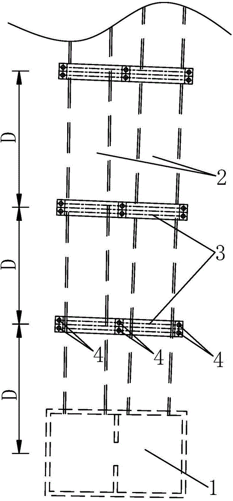
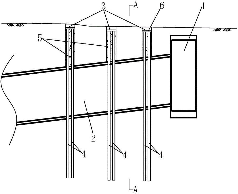
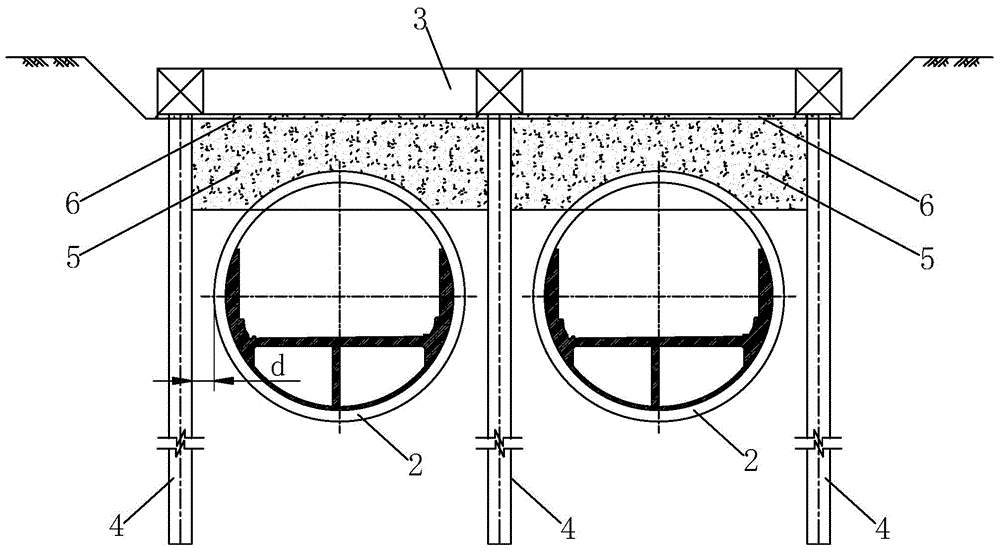
[0046] Example: such as figure 1 As shown, a shield tunnel continuous beam anti-floating structure provided in this embodiment includes several caps 3 arranged at intervals along the longitudinal direction of the shield tunnel 2, and all the caps 3 are arranged laterally on the shield tunnel 2 above, and the transverse centerlines of all the caps 3 are perpendicular to the vertical plane where the central axis of the shield tunnel 2 is; each of the caps 3 is provided with several sets of anti-corrosion Pulling piles 4, the number of groups of uplift piles 4 under the same cap 3 is the total number of shield tunnels 2 plus 1, and all groups of uplift piles 4 under the same cap 3 are respectively arranged in the corresponding The two sides of the shield tunnel 2, and two adjacent shield tunnels 2 share a group of uplift piles 4, the number of uplift piles 4 in each group of uplift piles 4 is at least 1, and each group of uplift piles The uplift piles 4 in 4 are also longitudina...


PUM


Abstract

The invention discloses a continuous beam type anti-floating structure of a shield tunnel. The continuous beam type anti-floating structure comprises a plurality of pile caps arranged longitudinally along the shield tunnel at intervals, the pile caps are transversely arranged above the shield tunnel, an uplift pile used for fixing is arranged below each pile cap, and a stratum reinforcing layer used for integrally connecting the pile caps, the uplift piles and the shield tunnel is arranged between the lower surface of the pile caps and the top surface of the shield tunnel. The continuous beam type anti-floating structure is applicable to the shield tunnel.

Description

technical field [0001] The invention relates to the field of shield tunnels, in particular to a continuous beam anti-floating structure of shield tunnels. Background technique [0002] The anti-floating design of the shield tunnel is an important design part of the shield tunnel, which directly affects the line design and the determination of the construction scale of the tunnel. safety factor requirements. Specifically, the anti-floating design of the shield tunnel needs to meet the anti-floating stability requirements, and the formula is as follows: [0003] G k F w ≥ K w [0004] In the formula: G k - Anti-buoyancy of the tunnel, which is composed of the anti-buoyancy provided by the tunnel's own weight, ballast or other measures; [0005] f w - buoyancy value of the tunnel; [0006] K w ——Safety factor of anti-floating...

Claims


Application Information

Patent Timeline
Patent Type & Authority Applications(China)
IPC IPC(8): E02D31/12E02D27/14E21D9/00
Inventor 肖明清龚彦峰鲁志鹏何应道孙峰龙凡蒋喆梁艳
Owner CHINA RAILWAY SIYUAN SURVEY & DESIGN GRP
Why Eureka
Try Eureka