A construction method of a shield tunnel

A technology of shield tunneling and construction method, which is applied in tunnels, infrastructure engineering, earthwork drilling, etc., can solve the problems of low anti-buoyancy, increased tunnel weight, and high cost, and achieves improved anti-buoyancy capacity, reduced engineering volume, Good anti-floating effect

Active Publication Date: 2018-01-02
CHINA RAILWAY SIYUAN SURVEY & DESIGN GRP
View PDF8 Cites 0 Cited by
  • Summary
  • Abstract
  • Description
  • Claims
  • Application Information

AI Technical Summary

Problems solved by technology

[0012] (1) The ground is heavily loaded and ballasted, and this anti-floating measure is generally difficult to achieve due to ground conditions during long-term operation;
[0013] (2) Use the useless space in the shield tunnel to fill concrete or other counterweight materials to increase the self-weight of the tunnel, but because the internal space of the shield tunnel is limited, the increased counterweight in the tunnel may not be able to completely overcome the buoyancy In some cases, it still cannot meet the safety requirements for anti-floating stability;
[0014] (3) Add a portal frame structure above the entire shield tunnel to increase the tunnel weight. The anti-floating measures require a large amount of work and high cost;
[0015] (4) Holes are opened in the internal structure of the shield tunnel, small uplift piles or anti-floating anchors are installed, and waterproof devices are installed. The anti-floating measures can increase the anti-buoyancy force less, and cannot fully meet the safety requirements for anti-floating stability
[0016] Therefore, several existing anti-floating measures have their own problems in actual construction, and cannot meet the actual construction needs.

Method used


Image

  • A construction method of a shield tunnel
  • A construction method of a shield tunnel
  • A construction method of a shield tunnel

Examples


Embodiment

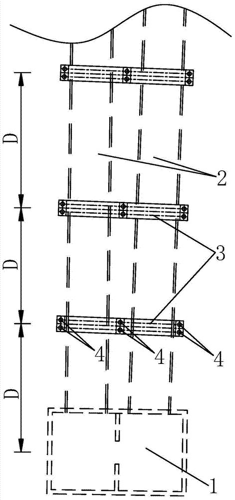
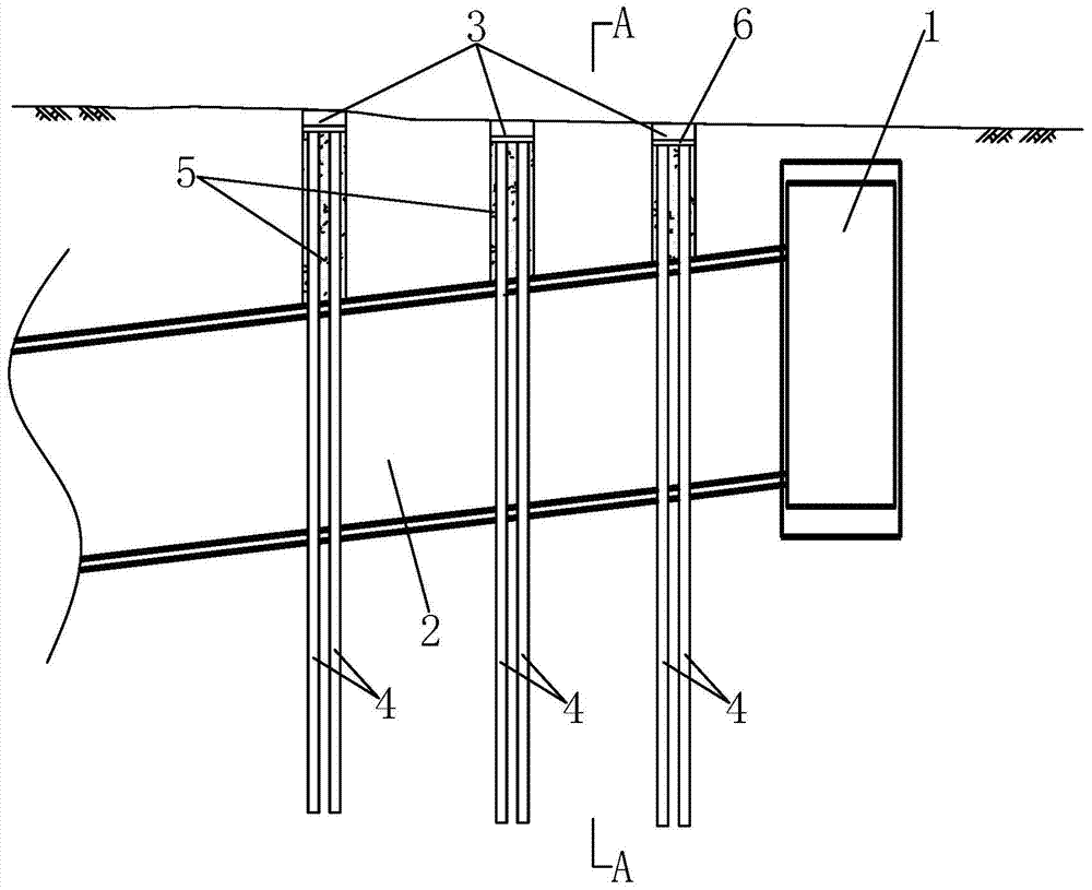
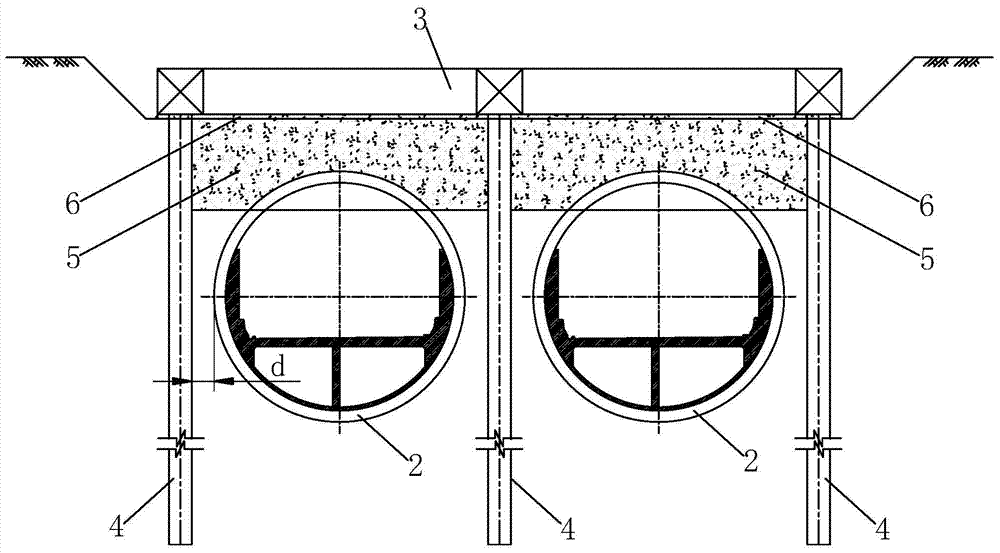
[0046] Example: such as figure 1 As shown, a shield tunnel continuous beam anti-floating structure provided in this embodiment includes several caps 3 arranged at intervals along the longitudinal direction of the shield tunnel 2, and all the caps 3 are arranged laterally on the shield tunnel 2 above, and the transverse centerlines of all the caps 3 are perpendicular to the vertical plane where the central axis of the shield tunnel 2 is; each of the caps 3 is provided with several sets of anti-corrosion Pulling piles 4, the number of groups of uplift piles 4 under the same cap 3 is the total number of shield tunnels 2 plus 1, and all groups of uplift piles 4 under the same cap 3 are respectively arranged in the corresponding The two sides of the shield tunnel 2, and two adjacent shield tunnels 2 share a group of uplift piles 4, the number of uplift piles 4 in each group of uplift piles 4 is at least 1, and each group of uplift piles The uplift piles 4 in 4 are also longitudina...


PUM


Abstract

A construction method for a shield tunnel, comprising: constructing uplift piles at intervals; constructing a ground reinforcement layer on the upper surface of the shield tunnel to be excavated; pouring a cushion on the ground reinforcement layer, and constructing a horizontal setting on the pouring cushion The caps of the uplift piles are anchored into the caps, and the ground reinforcement layer connects the caps, the uplift piles and the shield tunnel to be excavated. The caps are horizontal long beams, and two adjacent The distance D between platforms is 20-40m, and the method to determine the distance D is: calculate the remaining buoyancy force in the longitudinal direction of the shield tunnel; establish the continuous beam model of the longitudinal equivalent stiffness of the shield tunnel; The opening of shield tunnel segment lining shall not exceed 8mm, the dislocation between rings shall not exceed 15mm, the shear and tensile strength of bolts shall not exceed the design value, and the lining structure shall meet the strength and deformation requirements; shield tunnel excavation shall pass caps and uplift piles Assembling tunnel segments; constructing internal structures during excavation of shield tunnels or after penetration.

Description

technical field [0001] The invention relates to the field of shield tunnels, in particular to a construction method of shield tunnels. Background technique [0002] The anti-floating design of the shield tunnel is an important design part of the shield tunnel, which directly affects the line design and the determination of the construction scale of the tunnel. safety factor requirements. Specifically, the anti-floating design of the shield tunnel needs to meet the anti-floating stability requirements, and the formula is as follows: [0003] [0004] In the formula: G k - Anti-buoyancy of the tunnel, which is composed of the anti-buoyancy provided by the tunnel's own weight, ballast or other measures; [0005] f w - buoyancy value of the tunnel; [0006] K w ——Safety factor of anti-floating stability, check and calculate according to the most unfavorable situation, take 1.05 when the side friction resistance of the formation is not included; when the side friction re...

Claims


Application Information

Patent Timeline
Patent Type & Authority Patents(China)
IPC IPC(8): E02D31/12E02D27/14E21D9/00
Inventor 肖明清龚彦峰鲁志鹏何应道孙峰龙凡蒋喆梁艳
Owner CHINA RAILWAY SIYUAN SURVEY & DESIGN GRP
Why Eureka
Try Eureka