LNG underground tank base plate anti-floating decompression structure and construction thereof

A technology for underground storage tanks and base plates, which is applied in infrastructure engineering, construction, protection devices, etc., can solve the problems of high cost of anti-pulling anchor pile engineering, increasing the thickness of the base plate, and short construction period, so as to achieve a short construction period and reduce Crack resistance requirements, the effect of reducing the floatover force

Inactive Publication Date: 2018-07-27
ZHONGCHUAN NO 9 DESIGN & RES INST
View PDF5 Cites 4 Cited by
  • Summary
  • Abstract
  • Description
  • Claims
  • Application Information

AI Technical Summary

Problems solved by technology

[0003] At present, anti-floating measures for LNG (liquefied natural gas) underground storage tanks are mainly realized by increasing the thickness of the bottom plate and setting anti-floating anchor rods and anti-floating piles under the bottom plate. The uplift resistance of the uplift piles is used to resist the buoyancy of water. With the increase of LNG storage tanks, the diameter of the storage tanks exceeds 100m, and the engineering cost of increasing the thickness of the bottom plate and the installation of the uplift anchor piles is high, the construction period is short, and the anti-lift Poor floating effect

Method used


Image

  • LNG underground tank base plate anti-floating decompression structure and construction thereof
  • LNG underground tank base plate anti-floating decompression structure and construction thereof
  • LNG underground tank base plate anti-floating decompression structure and construction thereof

Examples


Embodiment 1

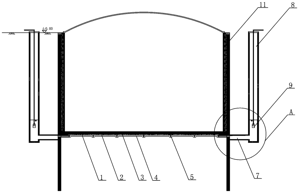
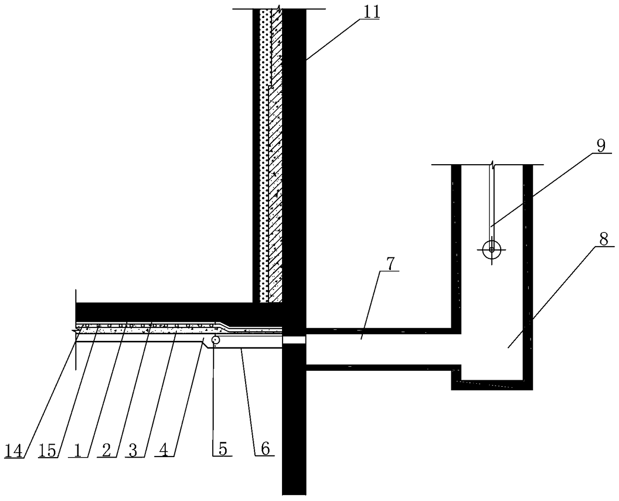
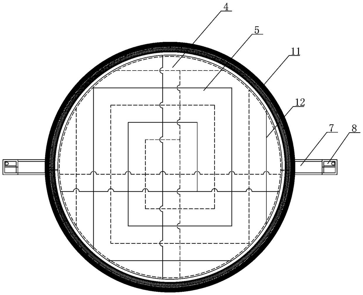
[0028] See attached image 3 , the project is a soil foundation, the vertical and horizontal spacing of the drainage pipes 12 is 12m, the thickness of the hydrophobic layer 4 is 600mm, and the drainage pipe 5 is set in the hydrophobic layer 4, and the underground seepage is collected through the drainage pipe 12 by the drainage channel 7 to the outside of the storage tank 11 After the water collecting well 8, the submersible pump 9 discharges the drainage pipe network 5, and its specific construction steps are as follows:

[0029] (1) Laying of permeable geotextiles

[0030] See attached figure 1 , excavated until the design elevation of the base plate 1 is -52.50m, the base surface is trimmed, and the permeable geotextile 6 is laid after meeting the flatness requirements. 6 is not destroyed.

[0031] (2) Laying of hydrophobic layer and installation of drainage pipes

[0032] A hydrophobic layer 4 of graded crushed stones is set on the permeable geotextile 6. The thickness...


PUM


Abstract

The invention discloses an LNG underground tank base plate anti-floating decompression structure and construction thereof. The LNG underground tank base plate anti-floating decompression structure ischaracterized in that a base plate is arranged on a hydrophobic layer provided with a hydrophobic pipe net, the hydrophobic pipe net communicates with water-collecting wells through hydrophobic channels, and the hydrophobic layer is arranged below a heat preservation layer of the base plate through a leveling layer; a temperature sensor and an electric heating pipe are embedded into the heat preservation layer; the hydrophobic pipe net is formed by criss-cross communication of grid-shaped water drainage pipes; and the water-collecting wells are arranged on the two sides of the base plate and communicate with the hydrophobic pipe net through the hydrophobic channels. Compared with the prior art, the LNG underground tank base plate anti-floating decompression structure has the advantages that safety is high, the building cost of projects is low, the construction period is short, and daily management is convenient; and the anti-cracking requirement for the base plate is reduced, the anti-floating stability requirement of the underground tank is met, ground surface settlement of surrounding environments can be controlled within the allowed scope, the anti-floating decompression effectis obvious, and the LNG underground tank base plate anti-floating decompression structure is particularly suitable for anti-floating design of deep underground space structures.

Description

technical field [0001] The invention relates to the field of underground structure anti-floating technology, in particular to an anti-floating and decompression structure for the floor of an LNG underground storage tank and its construction. Background technique [0002] With the acceleration of urbanization, the development of underground space has been paid more and more attention. For underground buildings such as large-scale underground shopping malls and underground parking garages, the buoyancy of the basement floor due to the penetration of groundwater and surface water has become an engineering project. focus in design. Anti-floating measures in underground engineering mainly adopt anti-floating anchors and anti-floating piles under the floor, and balance the buoyancy of groundwater by increasing the overlying weight of the underground structure or setting anti-floating anchors and anti-lift piles. The control requirements for uneven deformation are relatively high,...

Claims


Application Information

Patent Timeline
Patent Type & Authority Applications(China)
IPC IPC(8): E02D31/12E02D19/10
CPCE02D19/10E02D31/12
Inventor 金国龙林靖李华梅王鑫李昀周竝袁坚任家佳
Owner ZHONGCHUAN NO 9 DESIGN & RES INST
Why Eureka
Try Eureka