
Self-locking free telescopic column mechanism

A column and free technology, applied in the field of self-locking free telescopic column mechanism, can solve the problems of adjustment structure wear and damage, electronic product drop damage, finding inappropriate tools, etc., to avoid screw mechanism, prolong service life, The effect of ensuring safety

Active Publication Date: 2017-12-19
KUNSHAN HONGJIE ELECTRONICS CO LTD
View PDF9 Cites 0 Cited by
  • Summary
  • Abstract
  • Description
  • Claims
  • Application Information

AI Technical Summary

Problems solved by technology

[0002] The common retractable column mechanism adjusts the length of the column by locking and loosening the screws; if you want to adjust the length of the bracket after installation, you need to unscrew the upper screws one by one. Tighten one by one, the installation of this process often requires at least two people to cooperate, and it takes a long time, and sometimes even find inappropriate tools to adjust, which causes a lot of trouble to the user and cannot be more convenient. The use of the column may even cause the falling damage of the electronic products installed on the column, and the column mechanism is used for a long time, and after repeated friction, it is easy to cause wear and tear of the adjustment structure, or failure, and the service life is short

Method used


Image

  • Self-locking free telescopic column mechanism
  • Self-locking free telescopic column mechanism
  • Self-locking free telescopic column mechanism

Examples


Embodiment

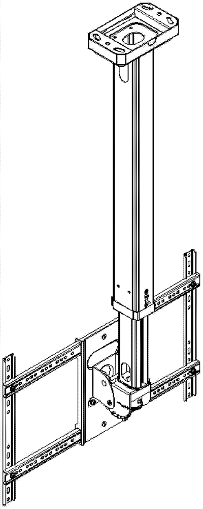
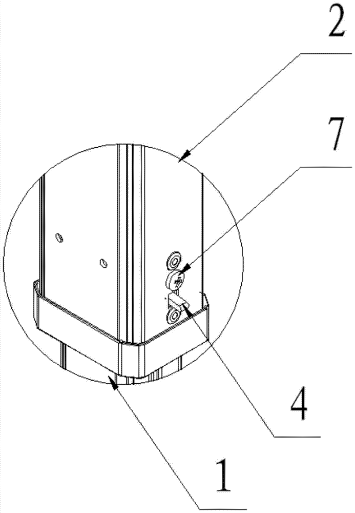
[0022] Embodiment: A self-locking free telescopic column mechanism, including a lower column 1, an upper column 2, a rack 3, a locking tooth 4, a fixing member 5 and an elastic member 6. Based on the actual use direction, the upper column 2. It can slide axially on the outer side of the lower column 1. The rack 3 is fixedly installed on the outer surface of the lower column 1. The rack 3 is provided with a number of sockets 8 at linear intervals along the length of the lower column 1. The fixing part 5 is fixed Installed on the inner surface of the upper column 2, the latch 4 is hinged on the fixing member 5, and one end of the latch 4 forms a ratchet structure 9, which can just extend into the socket 8 of the rack 3, and the ratchet structure 9 Only the upper column 2 is allowed to move in one direction relative to the lower column 1 along its length direction, and the other end of the locking tooth 4 protrudes to the outside of the upper column 2 along the perforation on the ...


PUM


Abstract

The invention discloses a self-locking stand column mechanism capable of stretching and retracting freely. The self-locking stand column mechanism capable of stretching and retracting freely comprises a lower stand column, an upper stand column, a rack, a clamping tooth, a fixing piece and an elastic piece. With the actual using direction as the criterion, the upper stand column can slide in the axial direction to be arranged outside the lower stand column in a sleeving mode, the rack is fixedly installed on the surface of the outer side of the lower stand column, a plurality of insertion holes are linearly formed in the rack in the length direction of the lower stand column at intervals, the fixing piece is fixedly installed on the surface of the inner side of the upper stand column, the clamping tooth is hinged to the fixing piece, a ratchet structure is formed at one end of the clamping tooth and can right stretch into one insertion hole of the rack, the ratchet structure only allows the upper stand column to move relative to the lower stand column in a unidirectional mode in the length direction of the upper stand column, the other end of the clamping tooth stretch out of the upper stand column along a through hole in the side wall of the upper stand column, and the ratchet structure of the clamping tooth is kept having the movement tendency to stretching into one insertion hole of the rack all the time by the elastic piece. The self-locking stand column mechanism capable of stretching and retracting freely is simple in structure, operation is easy, cooperative work of multiple people is not needed, and height adjustment safety of electronic products is guaranteed.

Description

technical field [0001] The invention relates to a cart, a suspended ceiling and a cantilever bracket with adjustable length or height, in particular to a self-locking free telescopic column mechanism. Background technique [0002] The common retractable column mechanism adjusts the length of the column by locking and loosening the screws; if you want to adjust the length of the bracket after installation, you need to unscrew the upper screws one by one. Tighten one by one, the installation of this process often requires at least two people to cooperate, and it takes a long time, and sometimes even find inappropriate tools to adjust, which causes a lot of trouble to the user and cannot be more convenient. The use of the column may even cause the falling damage of the electronic products installed on the column, and the column mechanism is used for a long time, and after repeated friction, it is easy to cause wear and tear of the adjustment structure, or failure, and the servi...

Claims


Application Information

Patent Timeline
Patent Type & Authority Patents(China)
IPC IPC(8): F16B7/14F16B7/18
CPCF16B7/14F16B7/1472
Inventor 常晓杰
Owner KUNSHAN HONGJIE ELECTRONICS CO LTD
Learn More