Top plate siding device, suspended ceiling and suspended ceiling installing method

A roof and top surface technology, which is applied to ceilings, building components, buildings, etc., can solve the problems of reducing installation speed, increasing construction cost, and inconvenience in the installation process, and achieves the effects of improving flatness, increasing construction speed, and reducing labor intensity

Active Publication Date: 2016-09-28
ZHEJIANG YASHA DECORATION
View PDF4 Cites 18 Cited by
  • Summary
  • Abstract
  • Description
  • Claims
  • Application Information

AI Technical Summary

Problems solved by technology

[0003] In the prior art, the installation of the last roof plate at the junction of the suspended ceiling and the wall is a problem that has not been effectively solved, so that various problems often occur after the installation of the last edge-receiving roof plate, specifically manifested in: first, the suspended ceiling The last edge-receiving roof on the roof is not at the same height as the other roofs on the ceiling, resulting in uneven ceilings; second, there are gaps at the joint between the last edge-receiving roof and the surrounding roof, which seriously affects the construction quality and often requires rework , greatly improving the construction strength; third, because the gap between the last roof and the adjacent wall is small, the space is limited during the installation of the last edge roof, which is extremely inconvenient and reduces the installation cost. speed, prolonging the construction period and increasing the construction cost

Method used


Image

  • Top plate siding device, suspended ceiling and suspended ceiling installing method

Examples


Embodiment Construction

[0019] The present invention will be described in detail below with reference to the embodiments. Wherein the same parts are denoted by the same reference numerals. It should be noted that the words "front", "rear", "left", "right", "upper" and "lower" used in the following description refer to the directions in the drawings, and the words "inner" and "outer" ” refer to directions towards or away from the geometric center of a particular part, respectively.

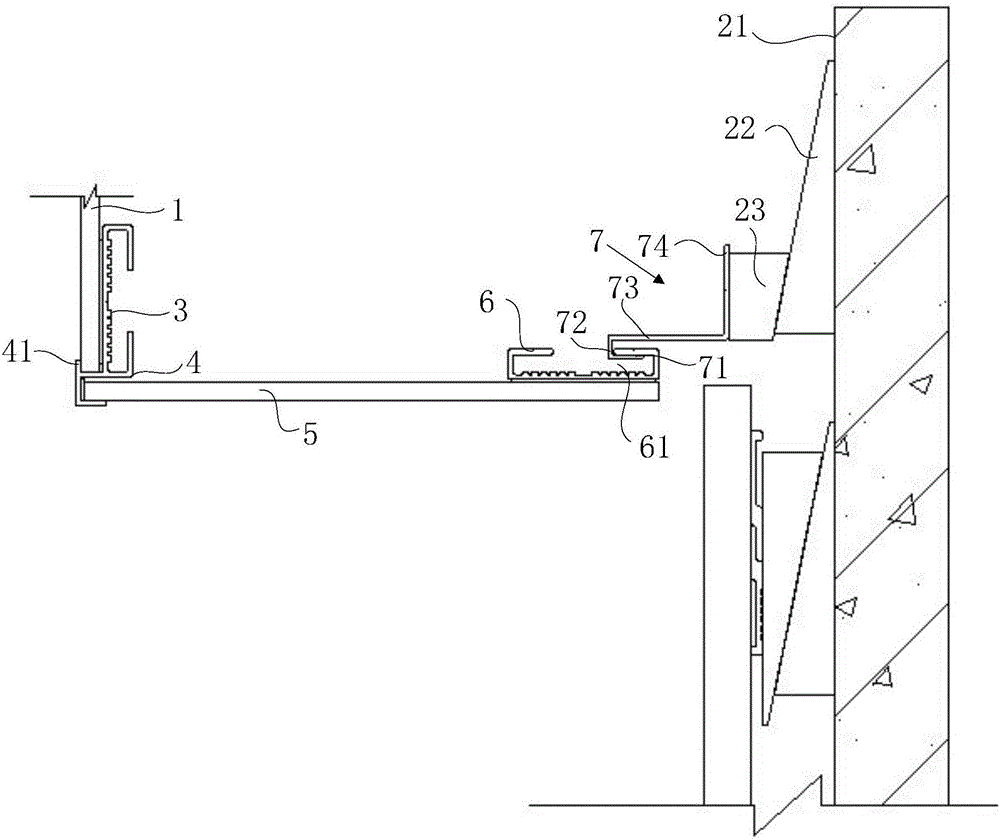
[0020] figure 1 It is a preferred embodiment of the structure of the top plate edge closing device provided by the present invention. like figure 1 As shown, the present invention provides a top plate edge closing device, comprising: a fixed vertical plate 1 and a fixed wall 2, a hanging keel 3, a retaining groove 4, a panel 5, a back hanging keel 6, and a hanging keel Bone 7.

[0021] Please refer to figure 1 , the vertical plate 1 and the wall surface 21 of the wall body 2 are arranged opposite to each other; the ...


PUM


Abstract

The invention discloses a top plate siding device, a suspended ceiling and a suspended ceiling installing method. The top plate siding device comprises a vertical plate and a wall face, wherein a suspending keel attaches to the vertical plate. A groove opening of a blocking groove right faces the wall face, the side face of the blocking groove is connected with the suspending keel, a positioning groove is formed in the blocking groove, and the vertical plate is located in the positioning groove. The first end of a face plate is arranged in the blocking groove, and the second end of the face plate extends towards the wall face. A back-suspended keel is connected with the second end of the face plate and is provided with a hooked connection groove. The first end of a hooked connection keel is fixed in the hooked connection groove, and the second end of the hooked connection keel is adjustably connected with the wall face. The invention further provides the suspended ceiling. The suspended ceiling comprises plaques and the top plate siding devices provided by the invention, wherein the plaques attach to the wall face. The suspended ceiling installing method is used for installing top plates on suspended ceilings of buildings. By the adoption of the top plate siding device, the suspended ceiling and the suspended ceiling installing method, the construction quality is improved, and the labor intensity of top plate installation is reduced.

Description

technical field [0001] The invention relates to the technical field of architectural decoration, in particular to a roof edge trimming device, a suspended ceiling and an installation method of the suspended ceiling. Background technique [0002] During the decoration process of the suspended ceiling, the joint of the suspended ceiling and the wall is generally closed by the structure of setting a circle of grooves at the closed mouth to achieve a better edge closing effect. [0003] In the prior art, the installation of the last top plate at the connection between the suspended ceiling and the wall is a problem that has not been effectively solved, so that various problems often occur after the installation of the last edged top plate, which is embodied in: first, the suspended ceiling The last edge-receiving top plate is not at the same height as the other roof panels on the ceiling, resulting in uneven height of the ceiling; secondly, there is a gap at the splicing between...

Claims


Application Information

Patent Timeline
Patent Type & Authority Applications(China)
IPC IPC(8): E04B9/30E04B9/06E04B9/22
CPCE04B9/06E04B9/22E04B9/30
Inventor 步挺周东珊钟诚王瑾程安顺郑波波
Owner ZHEJIANG YASHA DECORATION
Why Eureka
Try Eureka