
Petroleum pipe inner wall cleaning equipment

A technology for inner wall cleaning and petroleum pipelines, which is applied in the direction of cleaning hollow objects, cleaning methods and utensils, chemical instruments and methods, etc. It can solve the problems of inability to adjust, inability to adjust the cleaning, and the reduction of the use of oil, so as to ensure the effect of cleaning

Inactive Publication Date: 2019-08-20
卢李娜
View PDF9 Cites 20 Cited by
  • Summary
  • Abstract
  • Description
  • Claims
  • Application Information

AI Technical Summary

Problems solved by technology

Existing petroleum pipeline cleaning machines cannot be adjusted according to pipelines with different inner diameters, and the cleaning effect is poor, causing foreign matter in the pipeline to cause pipeline blockage, affecting the quality of petroleum, and reducing the use effect of petroleum
[0004] Existing cleaning machines cannot be adjusted and cleaned according to pipes with different inner diameters, and the cleaning effect is poor
After the oil pipeline has been used for a period of time, the inner wall will be very dirty and needs to be cleaned. At present, it is usually cleaned with a manual water nozzle, but manual cleaning with a water nozzle is not only time-consuming and laborious, but also has poor cleaning effects. Therefore, it is urgent to develop a water-saving Time-saving and labor-saving cleaning equipment for the inner wall of oil pipelines

Method used


Image

  • Petroleum pipe inner wall cleaning equipment
  • Petroleum pipe inner wall cleaning equipment
  • Petroleum pipe inner wall cleaning equipment

Examples


Embodiment Construction

[0024] The following will clearly and completely describe the technical solutions in the embodiments of the present invention with reference to the accompanying drawings in the embodiments of the present invention. Obviously, the described embodiments are only some, not all, embodiments of the present invention. Based on the embodiments of the present invention, all other embodiments obtained by persons of ordinary skill in the art without making creative efforts belong to the protection scope of the present invention.

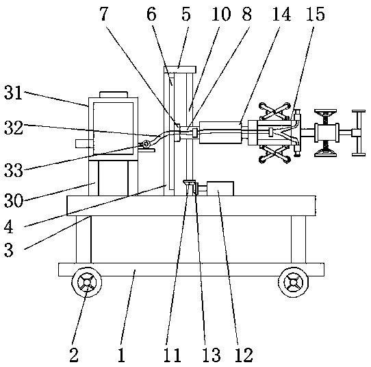
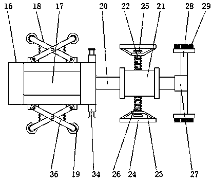
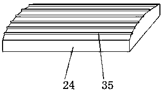
[0025] see Figure 1-5 , the present invention provides a technical solution: a cleaning device for the inner wall of an oil pipeline, including a base plate 1, a universal wheel 2 is provided at the bottom of the base plate 1, a bracket 3 is provided above the base plate 1, and a bracket 3 is provided on the bottom of the base plate 1 The top is provided with a riser 4, the top of the riser 4 is provided with a top plate 5, one side of the top plate 5 is prov...


PUM


Abstract

The invention discloses petroleum pipe inner wall cleaning equipment. The equipment comprises a base plate; universal wheels are arranged at the bottom of the base plate; a bracket is arranged above the base plate; a vertical plate is arranged at the top of the bracket; a top plate is arranged at the top of the vertical plate; a slide rail is arranged on one side of the vertical plate; a slide block is matched on the slide rail; a thread block is fixed on one side of the slide block; a screw rod is vertically downwards arranged at the bottom of the top plate; the thread block sleeves the screwrod; a first bevel gear fixedly sleeves the lower end of the screw rod; a first motor is arranged at the bottom of one side of the screw rod; a second bevel gear sleeves an output shaft of the firstmotor, and is in engaged connection with the first bevel gear; an electric extension rod is fixedly mounted on the side, far from the vertical plate, of the thread block; a cleaning device is mountedat the end part of the electric extension rod; the cleaning device comprises a cylindrical shell, a second motor and a scraping mechanism; and the end, penetrating through the cylindrical shell, of anoutput shaft of the second motor is fixedly connected with a rotating rod. The equipment is convenient to use, and can finish the cleaning process of flushing during removing of dirt.

Description

technical field [0001] The invention relates to the technical field of cleaning equipment, in particular to a cleaning equipment for the inner wall of an oil pipeline. Background technique [0002] A pipeline is a device used to transport gas, liquid or fluid with solid particles connected by pipes, pipe connectors and valves. Usually, after the fluid is pressurized by blowers, compressors, pumps and boilers, it flows from the high-pressure part of the pipeline to the low-pressure part, and it can also be transported by the pressure or gravity of the fluid itself. Pipes are widely used, mainly in water supply, drainage, heat supply, gas supply, long-distance transportation of oil and natural gas, agricultural irrigation, hydraulic engineering and various industrial devices. [0003] At present, the pipelines used for petroleum transportation need to be cleaned before use to avoid the residual impurities in the petroleum pipelines from affecting the quality of the petroleum....

Claims


Application Information

Patent Timeline
Patent Type & Authority Applications(China)
IPC IPC(8): B08B9/047
CPCB08B9/047
Inventor 卢李娜
Owner 卢李娜
Learn More