
Thermal Analyzer

一种热分析装置、加热炉的技术,应用在材料热分析、测量装置、分析材料等方向,能够解决无法可视地观察热分析试样变化等问题

Active Publication Date: 2015-09-16
HITACHI HIGH TECH SCI CORP
View PDF9 Cites 8 Cited by
  • Summary
  • Abstract
  • Description
  • Claims
  • Application Information

AI Technical Summary

Problems solved by technology

[0006] However, when the above-mentioned thermal analysis device is used, although the necessary thermal physical property values ​​can be detected, there is a problem that the change of the sample during the thermal analysis cannot be observed visually.

Method used


Image

  • Thermal Analyzer
  • Thermal Analyzer
  • Thermal Analyzer

Examples


Embodiment Construction

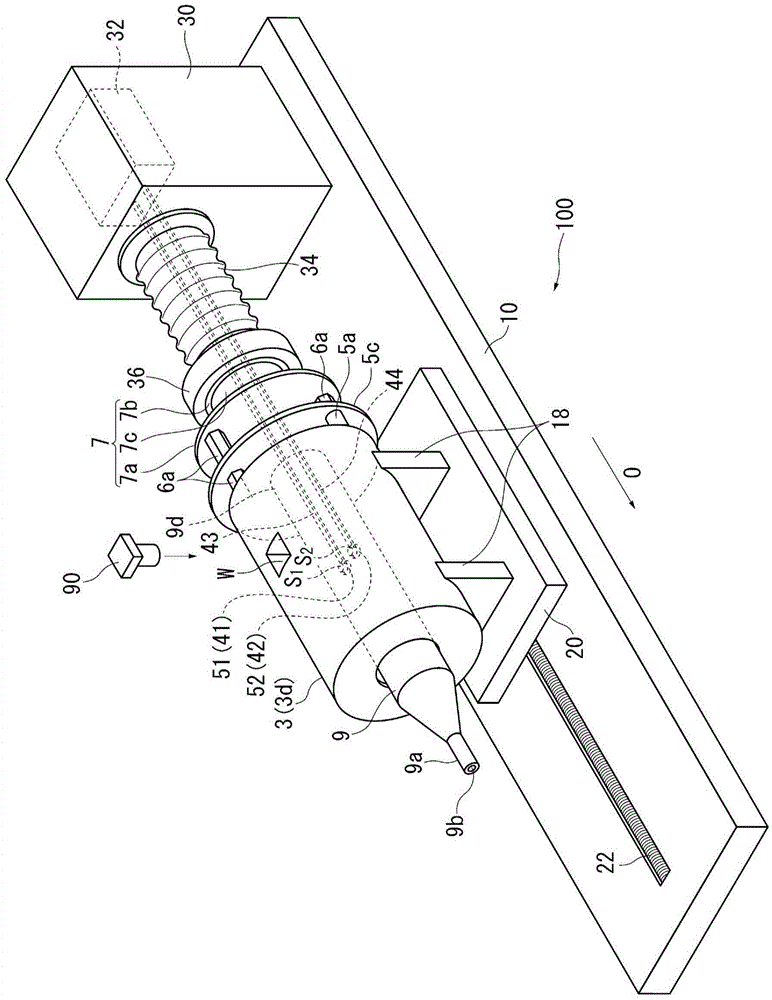
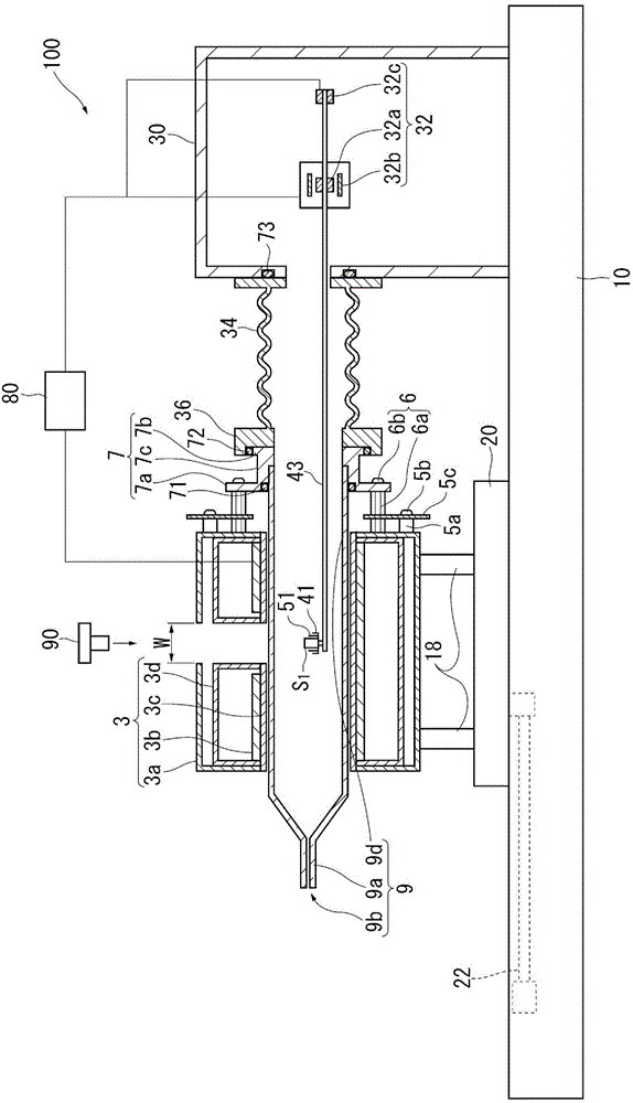
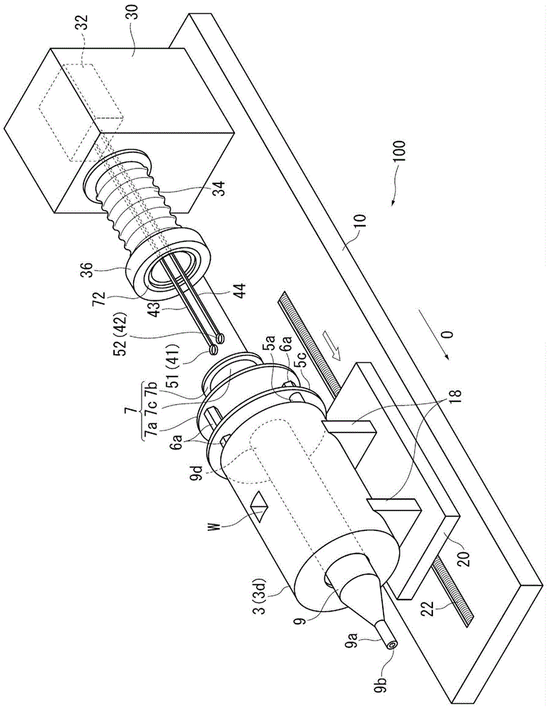
[0066] Hereinafter, embodiments of the present invention will be described with reference to the drawings. In addition, along the axial direction O, the side of the front end portion 9a of the furnace tube 9 is referred to as a "front end (side)", and the opposite side is referred to as a "rear end (side)". In addition, the surface facing the front end side in the axial direction O is referred to as a "front end facing surface", and the surface facing the rear end side is referred to as a "rear end facing surface".

[0067] figure 1 is a perspective view showing the configuration of the thermal analysis device 100 according to the first embodiment of the present invention, figure 2 is a cross-sectional view along the axial direction of the thermal analysis device 100 . image 3 It is a diagram showing a state in which a sample is placed or replaced in the thermal analysis device 100 . Figure 4 It is an exploded perspective view of the thermal analysis device 100 . also,...


PUM


Abstract

A thermal analyzer is provided with: a furnace tube; a sample holder; a heating furnace; a measurement chamber; and a measurement unit. The heating furnace comprises a fixing section to be fixed to the furnace tube. The furnace tube is configured to be attachable to and detachable from the heating furnace and provided with an engagement portion that is configured to be engaged with the fixing section at a variable position in the radial direction. A is configured to be detachable from the heating furnace and the furnace tube after inserting the furnace tube into the heating furnace and engaging the engagement portion of the furnace tube with the fixing section while the gap jig is interposed between the heating furnace and the furnace tube to maintain the gap between the heating furnace and the furnace tube in the radial direction to be in the predetermined distance.

Description

technical field [0001] The present invention relates to a thermal analysis device for heating a sample and measuring the physical change of the sample accompanying the temperature change. Background technique [0002] Conventionally, as a method of evaluating the temperature characteristics of a sample, a method called thermal analysis is performed in which a sample is heated and a physical change of the sample accompanied by a temperature change is measured. Thermal analysis is defined as JIS K 0129:2005 "General Principles of Thermal Analysis", and thermal analysis is a method for measuring the physical properties of a sample when the temperature of the measurement object (sample) is controlled by a program. Generally used thermal analysis has the following five methods: (1) differential thermal analysis (DTA) for detecting temperature (temperature difference), (2) differential scanning calorimetry (DSC) for detecting heat flow difference, (3) detecting mass (weight chang...

Claims


Application Information

Patent Timeline
Patent Type & Authority Applications(China)
IPC IPC(8): G01N25/00
CPCG01N25/00G01N5/04
Inventor 西村晋哉藤原宽仁
Owner HITACHI HIGH TECH SCI CORP
Learn More