A verification method for an electric energy metering device used in an automatic verification system for a direct-in three-phase smart electric energy meter

An electric energy metering device and automatic verification technology, applied in the field of instrumentation and electric measurement, can solve the problems of long calibration cycle time, large manual workload, low work efficiency, etc., achieve scientific design, ensure the transmission of electric energy value, and facilitate operation Effect

Active Publication Date: 2017-08-29
STATE GRID TIANJIN ELECTRIC POWER +1
View PDF4 Cites 0 Cited by
  • Summary
  • Abstract
  • Description
  • Claims
  • Application Information

AI Technical Summary

Problems solved by technology

At present, the method of checking during the period is to use the online detection of the electric energy meter to be tested. Dozens to hundreds of detection equipment are installed on the detection line to meet the online detection requirements of a large number of electric energy meters. The detection accuracy of the multiple detection equipment itself is calibrated It has become another difficult problem to ensure the detection accuracy of electric energy meters. Because the existing equipment itself is large in size, heavy in weight and difficult to move, it is necessary to manually carry the calibration equipment to disassemble, connect, and calibrate the testing equipment, often every calibration cycle Long time, heavy manual workload and low work efficiency

Method used


Image

  • A verification method for an electric energy metering device used in an automatic verification system for a direct-in three-phase smart electric energy meter
  • A verification method for an electric energy metering device used in an automatic verification system for a direct-in three-phase smart electric energy meter

Examples


Embodiment Construction

[0024] The present invention will be further described in detail below in conjunction with the accompanying drawings and through specific embodiments. The following embodiments are only descriptive, not restrictive, and cannot limit the protection scope of the present invention.

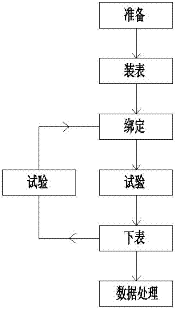
[0025] A verification method for an electric energy metering device used in an automatic verification system for a direct-in three-phase smart electric energy meter. The steps of the verification process on the automated assembly line verification system are as follows:

[0026] ⑴Preparation: Set up the standard electric energy meter of the direct-in three-phase smart electric energy meter. The accuracy of the meter is much higher than that of the task electric energy meter;

[0027] Make a special barcode for the standard electric energy meter to distinguish it from the normal meter; enter the information of the standard electric energy meter into the verification system, and automatically identify ...


PUM


Abstract

The invention relates to an electric energy metering device verification method for a straight-type three-phase intelligent electric energy meter automatic verification system. The verification process on an automatic assembly line verification system comprises a step of preparation in which information of a standard electric energy meter is inputted to a verification system, a step of meter mounting in which a standard electric energy meter tray is put in a binding position and randomly mixed with a normal task electric energy meter and flowed in an automatic verification line body, a step of binding in which an assembly line server binds the bar code of the standard electric energy meter and information of the tray according to a preset scheme, a step of test in which the automatic line carries out execution according to a scheduled test plan, a step of meter discharging in which a PLC automatically recognizes the standard electric energy meter on the tray according to the binding information, and the standard electric energy meter tray executes steps 3, 4 and 5 circularly, and a step of data processing in which verification data are derived. The method of the invention has the advantages that the design is scientific, the operation is convenient and quick, the result is accurate and reliable, period check can be carried out on the electric energy metering device or instrument equipment, and the electric energy value can be accurately and reliably transmitted.

Description

technical field [0001] The invention belongs to the fields of electrical measurement and instruments, in particular to a verification method for an electric energy metering device used in an automatic verification system for a direct-in type three-phase intelligent electric energy meter. Background technique [0002] Electric energy has become an indispensable and important energy source for the survival and development of human society. Almost all human activities are closely related to electricity, and electric energy meters are direct measuring instruments for detecting electric energy usage standards. How to ensure the calibration of electric energy meters The accuracy and efficiency of the test, and efforts to improve the calibration efficiency of the electric energy meter have become problems that need to be solved urgently by the measurement and testing departments at all levels. [0003] In order to maintain the reliability of electric energy metering devices and tes...

Claims


Application Information

Patent Timeline
Patent Type & Authority Patents(China)
IPC IPC(8): G01R35/04
Inventor 李野曹国瑞朱逸群滕永兴于学均陈刚郭景涛张一萌
Owner STATE GRID TIANJIN ELECTRIC POWER
Why Eureka
Try Eureka