Optical device and imaging device

An optical device, a technology for receiving light, used in optics, image communication, transportation and packaging, etc., can solve problems such as water migration, circuit board insulation failure, etc.

Active Publication Date: 2015-09-16
DENSO CORP
View PDF5 Cites 11 Cited by
  • Summary
  • Abstract
  • Description
  • Claims
  • Application Information

AI Technical Summary

Problems solved by technology

In such imaging devices, the occurrence of condensation on the circuit board may cause water droplets to migrate in the circuit board, causing insulation failure in the circuit board

Method used


Image

  • Optical device and imaging device
  • Optical device and imaging device
  • Optical device and imaging device

Examples


Embodiment Construction

[0030] Embodiments of the present disclosure are described below with reference to the accompanying drawings.

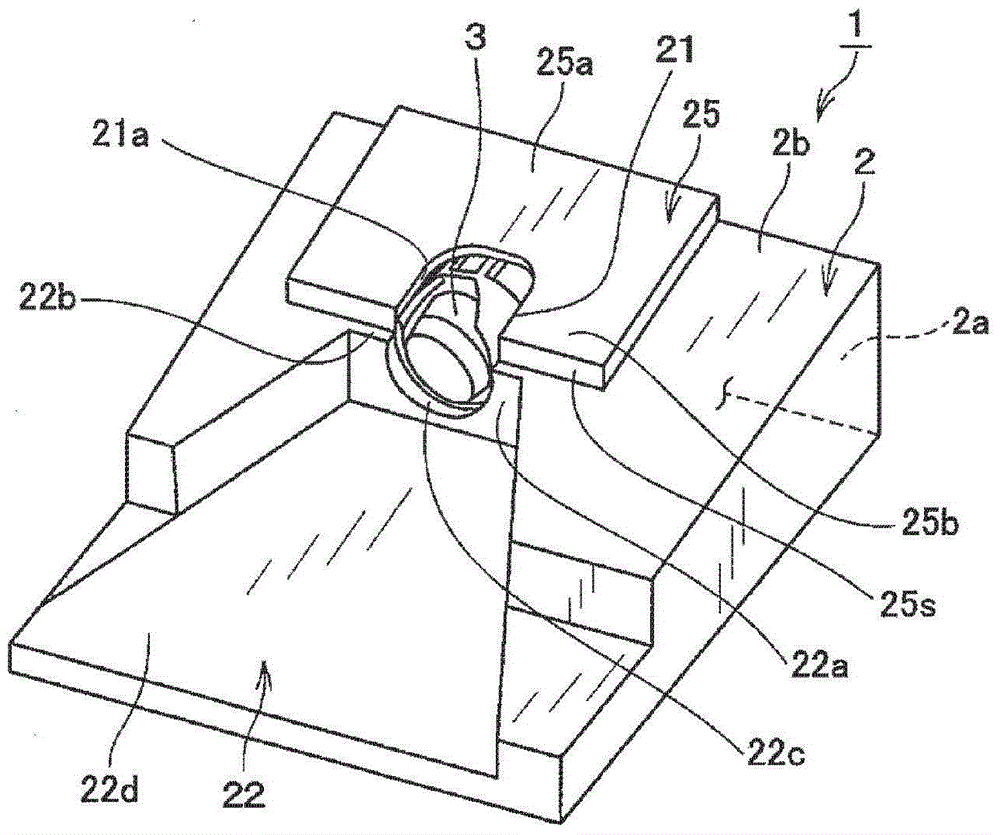
[0031] The imaging device 1 as an example of an optical device according to the embodiment is installed in, for example, a vehicle V in Figure 4 A portion of the vehicle V, such as the windshield, is shown in . The imaging device 1 picks up an image of an area in front of the vehicle V. As shown in FIG. The imaging device 1 also analyzes the picked-up images, and sends the analysis results to one or more ECUs installed in the vehicle V, such as a headlight control ECU and a lane departure detection ECU.

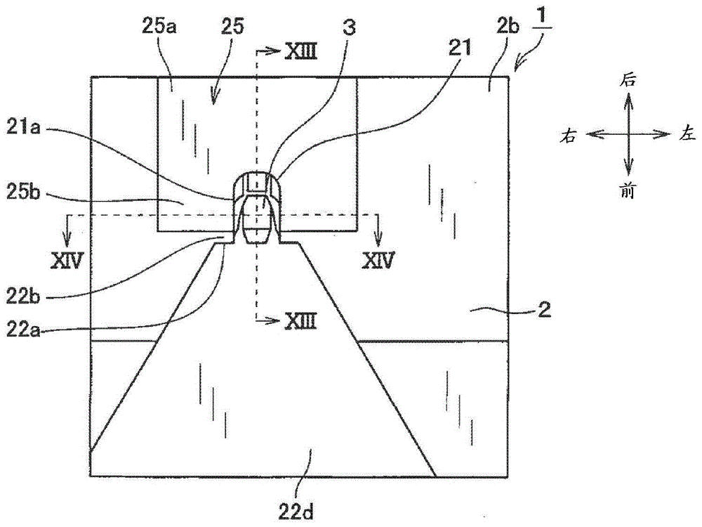
[0032] In the specification, the described front direction, rear direction, right direction and left direction show the front direction, rear direction, right direction and left direction of the vehicle V when the vehicle V travels in the front direction of the vehicle V. The front-rear direction corresponds to the longitudinal direction of the vehicle V, and the...


PUM


Abstract

In an optical device, a lens assembly includes a lens for receiving light and a holder for holding the lens. A circuit board performs at least one process based on the received light. A housing has an opening and is configured to house the lens assembly and the circuit board therein such that at least part of the circuit board faces the lens assembly, and the lens assembly is exposed via the opening. A mechanism for defining a passage located around the lens assembly to communicate with the opening. The passage guides air, entering an inside of the housing via the opening, so as not to be directed toward the circuit board.

Description

technical field [0001] The present disclosure relates to an optical device and an imaging device each equipped with a lens assembly, a circuit board, and a case housing the lens assembly and the circuit board. Background technique [0002] As an example of the optical device, there is an imaging device equipped with a lens assembly including a lens and a holder for holding the lens, a circuit board, and a housing that accommodates the lens assembly and the circuit board. In such imaging devices, the occurrence of condensation on the circuit board may cause water migration of water droplets in the circuit board, thereby causing insulation failure in the circuit board. [0003] There are several methods for reducing the risk of condensation occurring on circuit boards. The first method is to coat the circuit board with anti-drip material, and the second method is to fill the housing with a desiccant or inert gas. The third method is to design the housing with a closable chan...

Claims


Application Information

Patent Timeline
Patent Type & Authority Applications(China)
IPC IPC(8): H04N5/225G03B17/02
CPCG03B11/045H04N5/2252H04N5/2254B60R11/04B60R2011/0026G03B17/02H04N23/55G06V20/56H04N23/51H04N23/54
Inventor 和藤弘二
Owner DENSO CORP
Why Eureka
Try Eureka