
Synchronization control method used for space optical remote sensor servo system

A space optical remote sensing and servo system technology, applied in the field of aerospace remote sensors, can solve the problems that the scanning motion trajectory of the main rotation system of the space optical remote sensor cannot be changed, and the input of the main shaft can be changed.

Active Publication Date: 2015-09-23
BEIJING RES INST OF SPATIAL MECHANICAL & ELECTRICAL TECH
View PDF2 Cites 8 Cited by
  • Summary
  • Abstract
  • Description
  • Claims
  • Application Information

AI Technical Summary

Problems solved by technology

Compared with the non-coupled synchronization scheme, it can achieve higher synchronous control performance, but due to the compensation, the input of the main shaft will also be changed, which cannot meet the requirement that the scanning trajectory of the main rotation system of the space optical remote sensor remains unchanged.

Method used


Image

  • Synchronization control method used for space optical remote sensor servo system
  • Synchronization control method used for space optical remote sensor servo system
  • Synchronization control method used for space optical remote sensor servo system

Examples


Embodiment Construction

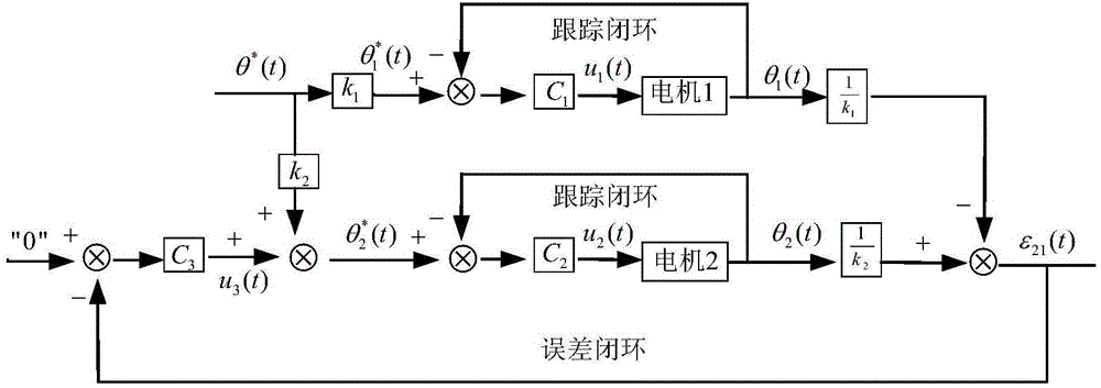
[0065] A synchronous control method for a two-axis follow-up system of a space optical remote sensor according to the present invention will be further explained and illustrated below in conjunction with the accompanying drawings.

[0066] The control principle of the inventive method is as figure 1 shown. Firstly, the scanning period T of the spindle motion system of the controlled mechanism and the effective scanning angle of view θ r , scan efficiency η, plan the motion curve of the main shaft, and obtain the reference angle θ of the main shaft at time t * (t), the spindle system is driven by a digital control method to move according to the position command signal; at the same time, according to the rotational speed ratio k of the spindle system and the follower shaft system, the position signal after the proportional transformation is obtained as the position command signal of the follower shaft system, The servo system is driven by the digital control method to comple...


PUM


Abstract

The invention provides a synchronization control method used for a space optical remote sensor servo system. Position servo commands of a main shaft scanning system and a slave shaft scanning system are designed by utilizing a preset index requirement; a main shaft tracking error controller is designed so that rotating scanning movement control performance of the main shaft system is enabled to meet a preset scanning linearity requirement; a slave shaft tracking error controller is designed so that the closed-loop characteristics of the slave shaft tracking error controller are enabled to be identical to those of the main shaft tracking error controller; and a synchronization error controller is designed so that the stable 0 tracking command of the two-shaft servo system is enabled to be stable, theta<z><cmd>xk<2> is added at the output end of the synchronization error controller and output of the main shaft tracking error controller is subtracted so that a synchronization control closed loop is formed, and synchronization control of the space optical remote sensor two-shaft servo system is completed. Compared with master command reference type synchronization and master-slave reference type synchronization, two-shaft synchronization movement precision is greatly enhanced by the method without influencing movement tracks of a main rotating system.

Description

technical field [0001] The invention designs a synchronous control method, in particular a synchronous control method for a space optical remote sensor servo system, and belongs to the technical field of aerospace remote sensors. Background technique [0002] In the imaging process of remote sensors in the field of space optics, in order to obtain a wider field of view, a scanning system is usually used to expand the range of incident light to increase the field of view on the ground and the width of the camera. Due to the small rotation range of the scanning mirror and the large angle between the incident angle and the mirror surface, the light is polarized and it is difficult to scan at a large angle. Therefore, it is hoped that the incident angle can be as small as possible in the design process. For this reason, it is generally necessary to design the main rotation system and the reflection system so that the incident light enters the camera parallel to the main rotatio...

Claims


Application Information

Patent Timeline
Patent Type & Authority Applications(China)
IPC IPC(8): G05B13/02
Inventor 李婧康建兵林喆李寅龙陈子印郝中洋宋莉张超
Owner BEIJING RES INST OF SPATIAL MECHANICAL & ELECTRICAL TECH
Learn More