
Chamfering detection mechanism

A detection mechanism and chamfering technology, applied in the direction of measuring/indicating equipment, metal processing machinery parts, metal processing equipment, etc., can solve the problems that are not suitable for the detection of large-scale small workpieces with chamfers, and are not suitable for batch detection. , to achieve the effect of accurate and reliable detection process and high detection efficiency

Active Publication Date: 2015-09-30
ZHUJI RUN TUO MECHANICAL AUTOMATION TECH
View PDF7 Cites 2 Cited by
  • Summary
  • Abstract
  • Description
  • Claims
  • Application Information

AI Technical Summary

Problems solved by technology

That is to say, it is necessary to put the above-mentioned device into the workpiece to detect, instead of putting the workpiece into the device, so the chamfering detection of the workpiece can only be detected one by one, which is not suitable for batch detection, especially not suitable for large Detection of chamfers on small-scale workpieces

Method used


Image

  • Chamfering detection mechanism
  • Chamfering detection mechanism
  • Chamfering detection mechanism

Examples


Embodiment Construction

[0024] The present invention will be further described in detail below in conjunction with the accompanying drawings and specific embodiments.

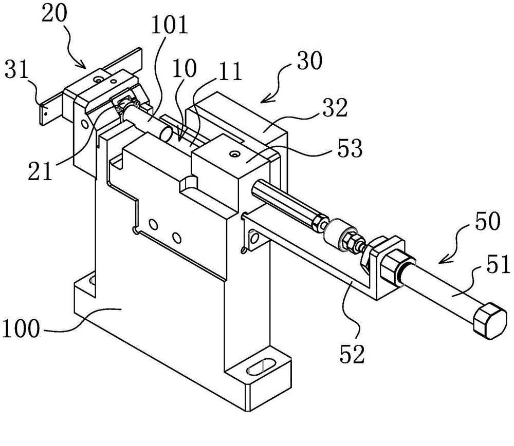
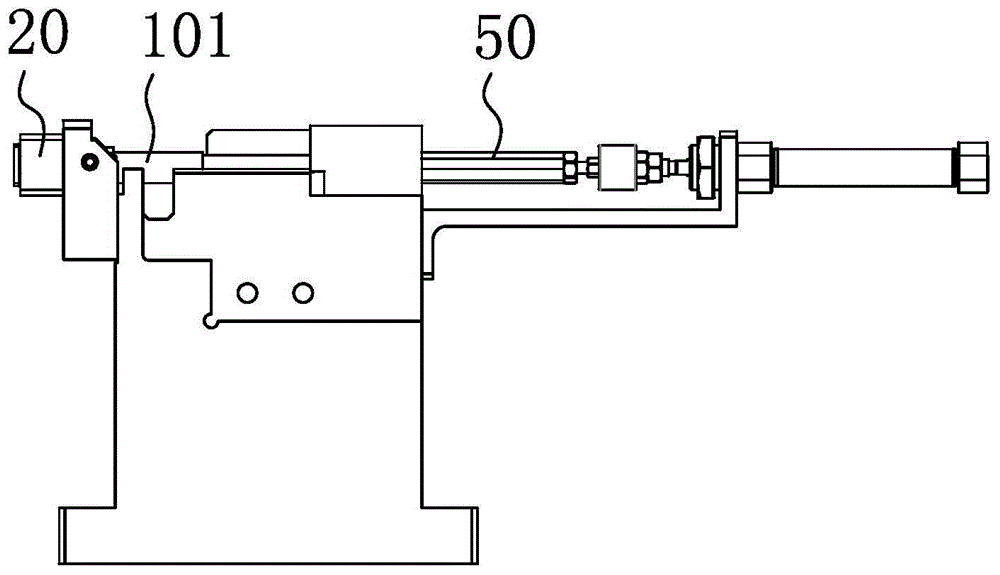
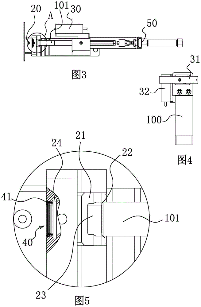
[0025] Such as Figure 1-4 As shown, a chamfering detection mechanism includes a base 100. The base 100 has a workpiece detection chamber 10 capable of placing a workpiece 101. On the base 100 and at the end of the workpiece detection chamber 10, a distance detector is also provided. device 20, when the workpiece 101 is put into the workpiece detection chamber 10 and moves toward the direction of the distance detector 20, the end of the workpiece with chamfers can enter the distance detector 20 and drive the distance detector 20 away from the workpiece The direction of the detection chamber 10 moves. The workpiece detection chamber 10 includes a bar-shaped workpiece positioning groove 11 arranged on the base 100 , and the surface of the workpiece positioning groove 11 is matched with the surface of the workpiece.

[0026] If the end...


PUM


Abstract

The invention belongs to the technical field of machinery manufacturing, and relates to a chamfering detection mechanism. The chamfering detection mechanism solves the technical problem that in the prior art, whether a workpiece is provided with a chamfering or not cannot be detected quickly. The chamfering detection mechanism comprises a base. The base is provided with a workpiece detection cavity for containing workpieces. The end, located in the workpiece detection cavity, of the base is provided with a distance detector. When the workpiece is placed into the workpiece detection cavity and moves towards the distance detector, the end of the workpiece with the chamfering can enter the distance detector and drive the distance detector to move in the direction away from the workpiece detection cavity. The chamfering detection mechanism can replace manual work to achieve chamfering detection, the detection process is accurate and reliable, and detection efficiency is high.

Description

technical field [0001] The invention belongs to the technical field of mechanical manufacturing, and relates to a chamfering detection mechanism, which is suitable for detecting whether a workpiece has chamfering. Background technique [0002] In order to remove the burrs produced by machining on the parts and to facilitate the assembly of the parts, chamfers are generally made on the ends of the parts. Generally, the function of chamfering is to remove burrs and make them beautiful. However, the chamfers specially pointed out in the drawings are generally the requirements of the installation process, such as the installation guide of the bearing, and some arc chamfers (or called arc transitions) can also reduce stress concentration and strengthen the shaft. The role of the strength of the class parts! In addition, it can also make assembly easier, usually before the end of processing. On agricultural machinery parts, especially the end faces of round fittings and round h...

Claims


Application Information

Patent Timeline
Patent Type & Authority Applications(China)
IPC IPC(8): B23Q17/20
CPCB23Q17/20
Inventor 俞才王
Owner ZHUJI RUN TUO MECHANICAL AUTOMATION TECH
Learn More