
Method for achieving low power consumption of timing photographing device for power transmission line passageway
A technology for taking pictures at regular intervals and for power transmission lines. It is applied in the parts of color TVs, parts of TV systems, TVs, etc., which can solve the problems of high cost, large volume and weight of lead-acid batteries, and large capacity and power of batteries and solar panels. and other problems, to achieve the effect of reducing other costs, reducing equipment power consumption, and prolonging service life
- Summary
- Abstract
- Description
- Claims
- Application Information
AI Technical Summary
Problems solved by technology
Method used
Image

Examples
Embodiment Construction
[0012] Embodiments of the present invention are further described below in conjunction with the accompanying drawings:
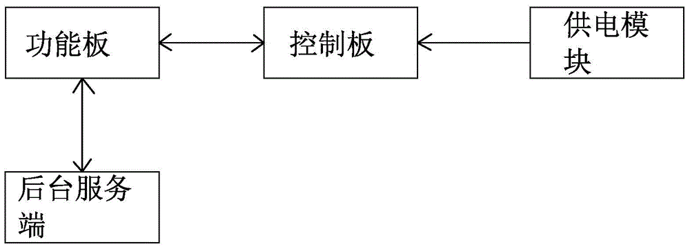
[0013] Such as figure 1 The method for realizing the low power consumption of the transmission line channel timing camera equipment shown in the figure,
[0014] (1) The power supply to the working unit is realized through the power supply module, the working unit is set at the power transmission line, and the working unit communicates with the background server;
[0015] (2) The working unit is the control board and the function board. The control board controls the working time of the function board and is responsible for timing the startup and shutdown;
[0016] (3) After the function board is started, it connects to the background server, performs system time calibration, and obtains the power on and off time, and then synchronizes the system clock, power on and off time with the control board, and the function board collects information regularly durin...
PUM
 Abstract
Description
Claims
Application Information