

Bar code reading device with reflector
A reflector and equipment technology, applied in the field of barcode reading, can solve the problems of increased lighting system components, poor control of light, and large equipment volume, and achieve the effects of reducing equipment volume, reducing the impact of glare, and reducing equipment power consumption
- Summary
- Abstract
- Description
- Claims
- Application Information
AI Technical Summary
Problems solved by technology
Method used
Image

Examples
Embodiment 1
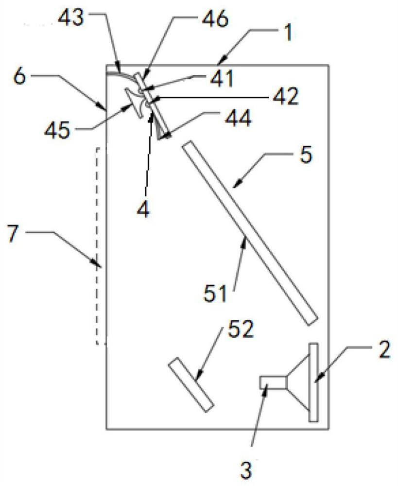
[0030] Such as figure 1 As shown, a barcode reading device with a reflector includes the following components:
[0031] Housing 1, the front panel of the housing 1 is provided with an opening;
[0032] The image sensor 2 is arranged at the lower part of the rear end of the housing 1 , and the lens 3 is arranged in front of the photosensitive surface of the image sensor 2 . The image sensor 2 is electrically connected to a decoding board, which is not shown in the drawings, and the decoding board includes an MCU or a barcode decoding chip.
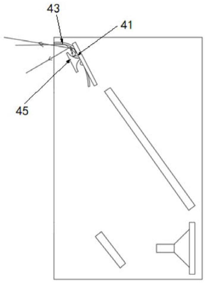
[0033] The lighting module 4 is located above the interior of the casing 1 and is close to the front end. The lighting module 4 includes: a first LED 41 , a second LED 42 , a first reflector 43 , a second reflector 44 , and a third reflector 45 , printed circuit board 46 .
[0034] The included angle between the printed circuit board 46 and the vertical direction is a first angle, and the range of the first angle is between 20° and 50°. ...
PUM
 Abstract
Description
Claims
Application Information