
Flowmeter

A flow measurement and equipment technology, applied in the field of flow measurement equipment, can solve problems such as insufficient pressure balance, and achieve the effect of simplifying the release

Inactive Publication Date: 2015-09-30
AVL LIST GMBH
View PDF9 Cites 8 Cited by
  • Summary
  • Abstract
  • Description
  • Claims
  • Application Information

AI Technical Summary

Problems solved by technology

However, as soon as the piston rests against the stop, the piston is held on the stop by the system pressure, so that in order to return to the neutral position again, the pressure equalization is not enough, but other measures must be taken.

Method used


Image

  • Flowmeter
  • Flowmeter

Examples


Embodiment Construction

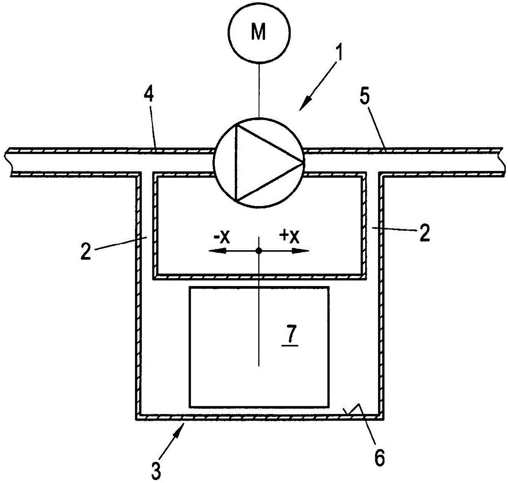
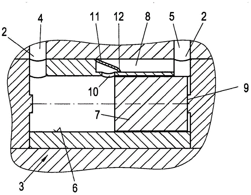
[0008] according to figure 1 The flow measuring device has a positive displacement flowmeter 1 , which can be implemented, for example, as a known gear flowmeter, to which a differential pressure sensor 3 is connected in parallel in a bypass line 2 . A motor M connected in rotation to the positive displacement flowmeter 1 is controlled as a function of the differential pressure determined at the differential pressure sensor 2 between the inflow side 4 and the outflow side 5 of the positive displacement flowmeter 1 to achieve a constant differential pressure compensation. The differential pressure sensor 3 has a freely movable piston 7 in the cylinder area 6 of the bypass line 2 , whose deflection due to the resulting differential pressure is determined and used to control the motor of the positive displacement flowmeter 1 M. The offset −x / +x of the piston 7 from its central position according to the illustration is measured or monitored by known sensor systems, for example by...


PUM


Abstract

In a flowmeter having a displacement meter (1), a pressure different sensor (3) connected in parallel has a bypass channel (8) which, when the piston (7) is at the maximum travel stop (9) thereof, enables a connection between the inflow and outflow sides (4, 5). A check valve (11) which prevents the return flow from the outflow side to the inflow side (5, 4) and therefore enables a purely pressure-induced return of the piston (7) is arranged in the bypass channel (8).

Description

technical field [0001] The present invention relates to a flow measuring device, the flow measuring device has a volumetric flowmeter, a differential pressure sensor is connected in parallel to the volumetric flowmeter in a bypass line, wherein the motor connected in rotation with the volumetric flowmeter is controlled by The differential pressure determined by the differential pressure sensor between the inflow side and the outflow side of the positive displacement flowmeter is controlled to achieve a constant differential pressure balance, wherein the differential pressure sensor has a free movement in the cylinder area of ​​the bypass line The piston whose deflection due to the pressure difference is determined and used to control the motor of the positive displacement flowmeter, and the bypass line has a bypass channel, when the piston on the outflow side rests on the maximum stroke stop When blocked, the bypass channel releases the communication between the inflow side an...

Claims


Application Information

Patent Timeline
Patent Type & Authority Applications(China)
IPC IPC(8): G01F3/10G01F15/02G01F15/00
CPCG01F3/10G01F15/005G01F15/026
Inventor O·德施密特
Owner AVL LIST GMBH
Learn More