Al technical title is built by PatSnap Al team. It summarizes the technical point description of the patent document.
A technology of synthetic aperture laser and orthogonal polarization, applied in the direction of re-radiation, instruments, measuring devices, etc., can solve the problems of high assembly accuracy and stability, affecting imaging results, etc., to reduce assembly accuracy and stability requirements, high sensitivity, and the effect of eliminating phase error interference
Active Publication Date: 2017-07-14
SHANGHAI INST OF OPTICS & FINE MECHANICS CHINESE ACAD OF SCI
View PDF2 Cites 0 Cited by
Summary
Abstract
Description
Claims
Application Information
AI Technical Summary
This helps you quickly interpret patents by identifying the three key elements:
Problems solved by technology
Method used
Benefits of technology
Problems solved by technology
However, this scheme only places an optical phase modulator on one of the two paths. The optical elements passed by the two orthogonally polarized paths are different, and the initial phase between the pulses will change, which will introduce a phase error between the two orthogonally polarized paths and affect the imaging results; And this scheme uses a large number of space optical body elements, so that the system has higher requirements for assembly accuracy and stability
Method used
Image
Click on the blue label to locate the original text in one second.
Reading with bidirectional positioning of images and text.
Examples
Embodiment Construction
[0026] The present invention will be described in further detail below in conjunction with the accompanying drawings and embodiments, but the protection scope of the present invention should not be limited thereby.
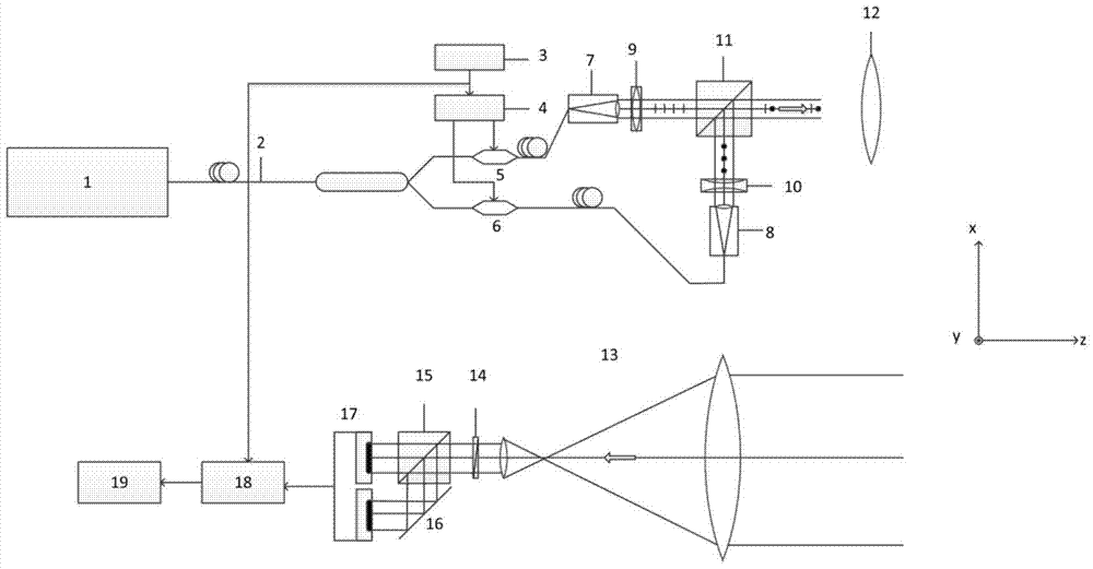
[0027] figure 1 It is a schematic diagram of the principle of the transmitting end of the present invention. As can be seen from the figure, the transmitting end of the present invention includes a laser light source 1, an optical fiber polarization beam splitter 2, a microwave signal waveform generator 3, a microwave amplifier 4, a first optical phase modulator 5, a second optical phase modulator 6, a A fiber collimator 7, a second fiber collimator 8, a first along-track cylindrical lens 9, a second along-track cylindrical lens 10, an emission polarization beam combiner 11 and an emission primary mirror 12; The receiving end includes receiving telescope 13, receiving half-wave plate 14, receiving polarization beam splitter 15, reflector 16, balance detector 17; ...
PUM
Abstract
Provided is a phase encoding cross-polarization synthetic aperture laser imaging radar which comprises a laser light source, a fiber polarization beam splitter, a first optical phase modulator, a second optical phase modulator, a microwave signal waveform generator, a microwave amplifier, a first fiber collimator, a second fiber collimator, a first along-rail cylindrical lens, a second along-rail cylindrical lens, a emission polarization beam combiner, an emission primary mirror, a receiving telescope, a receiving half-wave plate, a receiving polarization beam splitter, a reflector, a balance detector, an A / D converter, and a signal acquiring and processing computer. The phase encoding cross-polarization synthetic aperture laser imaging radar have same advantages with an orthophoria synthetic aperture laser imaging radar, is not provided with a moving optical element so as to avoid errors and noise of mechanical elements for driving an optical element to move, uses reciprocal half-code phase modulation, reduces voltage values loaded onto the optical phase modulators, changes the encoding speed of the microwave signal generator, namely changes the system cross-rail resolution, and is high in flexibility.
Description
technical field [0001] The invention relates to a synthetic aperture laser imaging radar, in particular to a phase coded orthogonal polarization synthetic aperture laser imaging radar. Background technique [0002] In the field of coherent range-Doppler lidar imaging and scanning 3D imaging lidar, various phase encoding waveforms are usually used to obtain the relative distance information of the detection target, and the waveform compression processing based on matched filtering is the key to obtaining relative distance information from the phase encoding waveform The only means of information processing. [0003] Prior art [1] (Beck S M, Buck J R, Buell W F, et al.. Synthetic-aperture imaging laser radar: laboratory demonstration and signal processing [J]. Applied Optics, 2005, 44 (35): 7621-7629) The synthetic aperture laser imaging radar works in the side-view mode, emits chirp laser pulses, performs optical heterodyne reception with the chirp pulses that are locally sp...
Claims
Application Information
Patent Timeline
Application Date:The date an application was filed.
Publication Date:The date a patent or application was officially published.
First Publication Date:The earliest publication date of a patent with the same application number.
Issue Date:Publication date of the patent grant document.
PCT Entry Date:The Entry date of PCT National Phase.
Estimated Expiry Date:The statutory expiry date of a patent right according to the Patent Law, and it is the longest term of protection that the patent right can achieve without the termination of the patent right due to other reasons(Term extension factor has been taken into account ).
Invalid Date:Actual expiry date is based on effective date or publication date of legal transaction data of invalid patent.
Patent Type & Authority Patents(China)
IPC IPC(8): G01S17/89G01S7/484G01S7/481
CPCG01S7/4818G01S7/484G01S17/90
Inventor 孙建锋蔡光宇卢智勇李光远张国马小平刘立人
Owner SHANGHAI INST OF OPTICS & FINE MECHANICS CHINESE ACAD OF SCI