
Designing method for side anchor mouth with functional area separating structure

A technology of regional structure and design method, applied in the directions of ship components, ships, transportation and packaging, etc., can solve the problems of difficulty in meeting the needs of the ship type, single side anchor lips, etc., to shorten the design cycle and avoid the effect of anchor stuck.

Active Publication Date: 2015-10-14
JIANGSU UNIV OF SCI & TECH
View PDF5 Cites 14 Cited by
  • Summary
  • Abstract
  • Description
  • Claims
  • Application Information

AI Technical Summary

Problems solved by technology

However, the above four patents introduce the design of the side anchor lip by using the specified section of the side anchor lip. The designed side anchor lip has a single nature, and it is difficult to meet the needs of all ship types.
Currently there is no public report on the design of side anchor lip and functional area

Method used


Image

  • Designing method for side anchor mouth with functional area separating structure
  • Designing method for side anchor mouth with functional area separating structure
  • Designing method for side anchor mouth with functional area separating structure

Examples


Embodiment Construction

[0036] The technical solution of the present invention will be further introduced below in combination with specific embodiments.

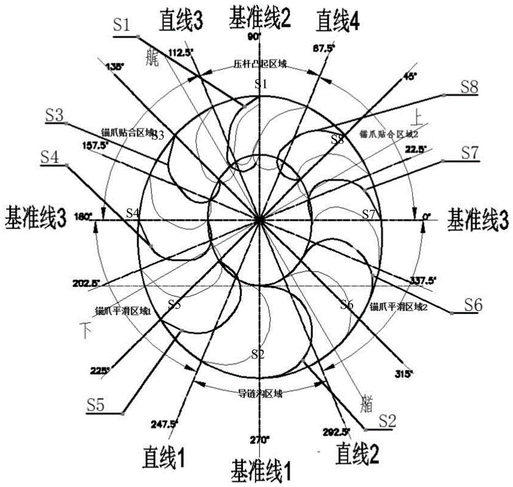
[0037] A side anchor lip is an anchor lip located on one side of the hull, for example on the port or starboard side. A kind of side anchor lip design method with sub-functional area structure provided by the present invention comprises the following steps:

[0038] Step 1: Determine the angles of the chain guide groove area of ​​the side anchor lip, the pressure rod raised area, the first fluke fitting area, the second fluke fitting area, the first fluke smooth area and the second fluke smooth area scope;

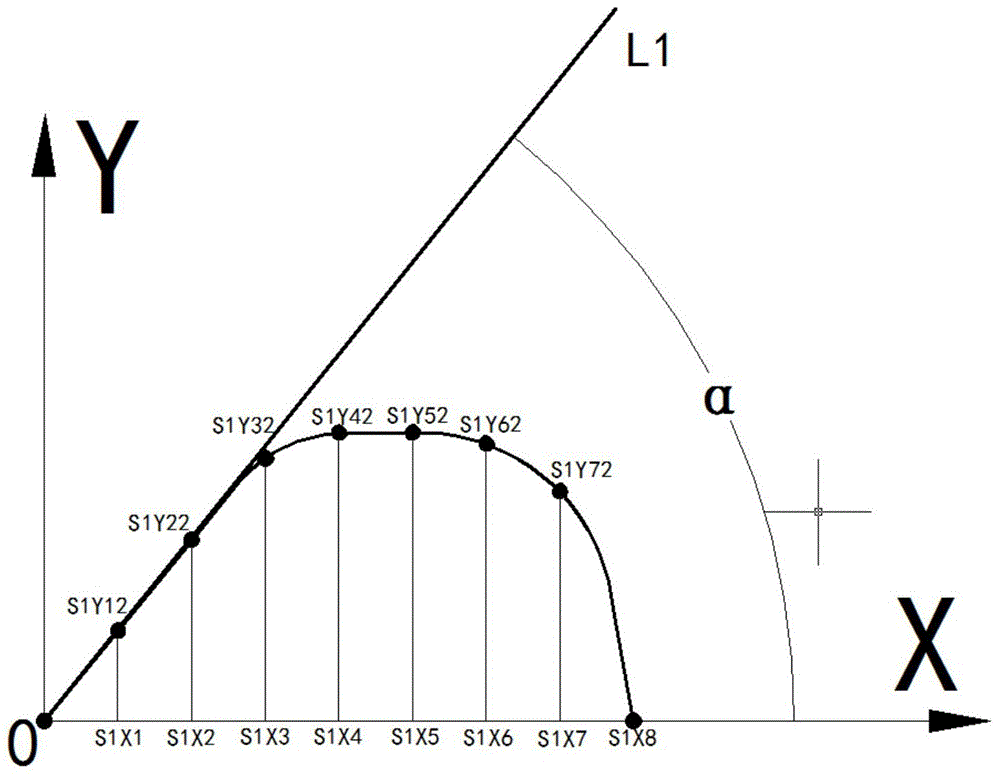
[0039] Step 2: Design the side anchor lip section in the area of ​​the chain guide groove;

[0040] Step 3: Design the side anchor lip section in the raised area of ​​the pressure bar;

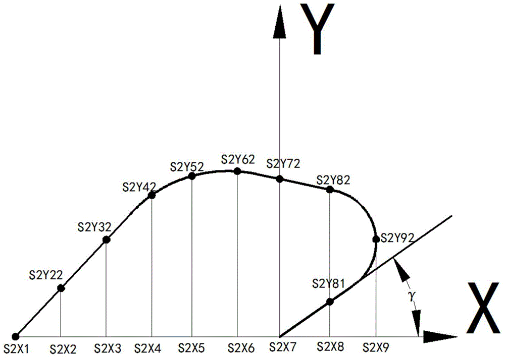
[0041] Step 4: Design the side anchor lip sections in the smooth area of ​​the first fluke and the smooth area of ​​the second fluke;

[0042] Step 5: Des...


PUM


Abstract

The invention discloses a designing method for a side anchor mouth with a functional area separating structure. The designing method comprises the six steps that 1, the angle ranges of a chain guide groove area, a pressing rod protrusion area, a first anchor jaw fitting area, a second anchor jaw fitting area, a first anchor jaw smooth area and a second anchor jaw smooth area of the side anchor mouth are determined; 2, the side anchor mouth section in the chain guide groove area is designed; 3, the side anchor mouth section in the pressing rod protrusion area is designed; 4, the side anchor mouth sections in the first and second anchor jaw smooth areas are designed; 5, the side anchor mouth sections in the first and second anchor jaw fitting areas are designed; and 6, the side anchor mouth sections in the adjacent areas are in smooth transition. According to the designing method for the side anchor mouth with the functional area separating structure, the side anchor mouth designing period can be shortened; the anchor clamping phenomenon and collision between anchor jaws and a ship are prevented in the anchor pulling process; complete fit between the anchor jaws and the anchor mouth is ensured; the requirements of all types of ships can be met.

Description

technical field [0001] The invention relates to a method for designing a side anchor lip, in particular to a method for designing a side anchor lip with a sub-functional area structure. Background technique [0002] With the development of the shipbuilding industry, the cost of shipbuilding has been reduced. At present, the design process of anchored ships is cumbersome and untargeted, and the occurrence of stuck anchors and incomplete fit cannot be avoided. [0003] After searching the existing technical literature, it was found that the Chinese invention patent publication number: CN202765234U, name: a spiral anchor lip, the technology self-report uses the anchor lip section to form a spiral surface. [0004] Chinese Invention Patent Publication No.: CN201110234291, Name: A Design and Manufacture Method for a Circular Anchor Lip and a Right Conical Anchor Platform. A part of the surface developed by the normal conic. [0005] Chinese Invention Patent Publication No.: CN2...

Claims


Application Information

Patent Timeline
IPC IPC(8): B63B21/14B63B9/00
Inventor 刘志强王国良柳鹏纪飞飞钱兴达
Owner JIANGSU UNIV OF SCI & TECH
Learn More