Token bucket limiting speed method and apparatus

A token bucket and token technology, which is applied in digital transmission systems, electrical components, transmission systems, etc., can solve the problems of unguaranteed speed limit quality of long packets, and achieve the effect of improving service quality.

Active Publication Date: 2015-10-14
SANECHIPS TECH CO LTD
View PDF2 Cites 25 Cited by
  • Summary
  • Abstract
  • Description
  • Claims
  • Application Information

AI Technical Summary

Problems solved by technology

[0004] However, in practical applications, since the message rate is often greater than the rate of adding tokens, the token bucket is in a state of being "empty" for a long time, so the r

Method used


Image

  • Token bucket limiting speed method and apparatus
  • Token bucket limiting speed method and apparatus
  • Token bucket limiting speed method and apparatus

Examples


Example Embodiment

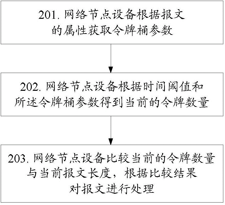
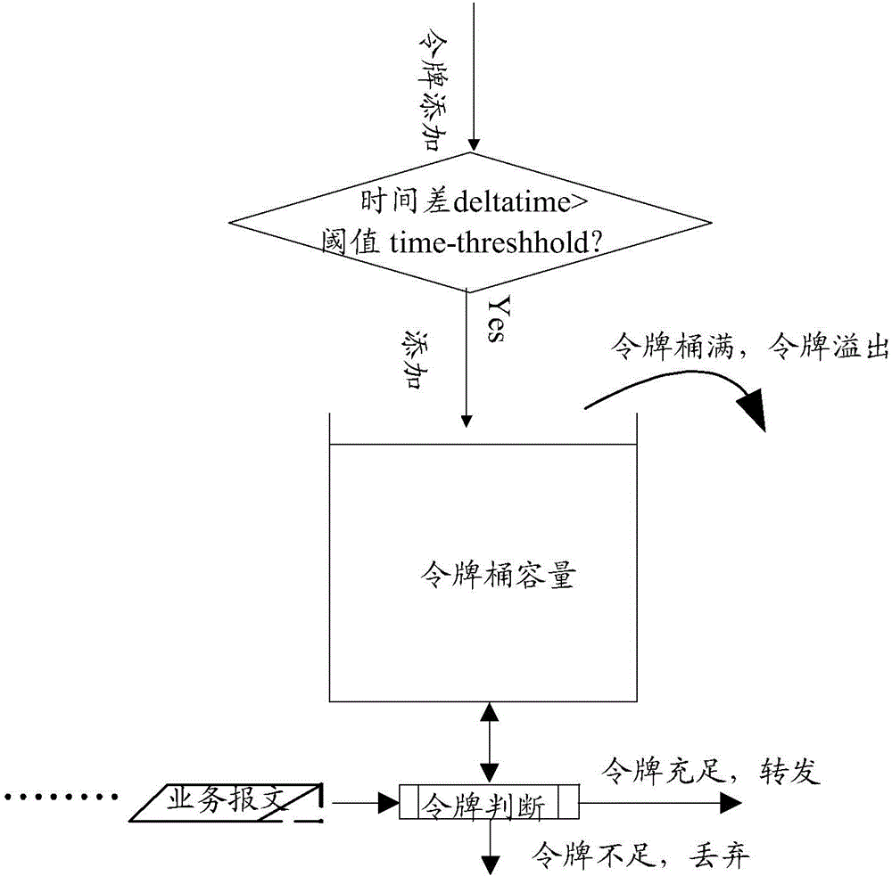
[0036] In the embodiment of the present invention, the network node device obtains the token bucket parameters according to the attributes of the message; then obtains the current number of tokens according to the set time threshold and the token bucket parameters; compares the current number of tokens with the current The length of the message, the message is processed according to the comparison result.

[0037] Hereinafter, the present invention will be further described in detail through the accompanying drawings and specific embodiments.

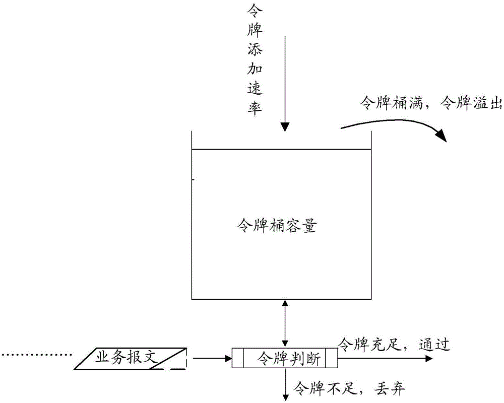
[0038] The flow of the token bucket rate limiting method provided by the embodiment of the present invention is as follows figure 1 As shown, the method mainly includes the following steps:

[0039] Step 201: The network node device obtains token bucket parameters according to the attributes of the message;

[0040] Specifically, the network node device finds the token bucket parameters carried in the message data packet through the index of th...


PUM


Abstract

Disclosed are a method and apparatus for limiting a rate by means of a token bucket, and a computer storage medium. The method comprises: a network node device obtains a token bucket parameter according to an attribute of a packet; then, obtains a current token quantity according to a time threshold and the token bucket parameter; and compares the current token quantity with a current packet length, and processes the packet according to a comparison result.

Description

technical field [0001] The invention relates to the field of quality of service (QoS, Quality of Service) of a data network, in particular to a token bucket rate limiting method and device. Background technique [0002] In an existing data network, due to the burstiness of message traffic, network congestion often occurs. One way to avoid network congestion is to limit the packet rate at the receiving end. If the packet rate is lower than the specified rate, the packet will be received normally; if the packet rate exceeds the specified rate, the packet will be discarded. . [0003] The existing method is to use the token bucket to limit the rate of the message. The standards of the token bucket algorithm include RFC2697 and RFC2698, that is, single-rate three-color double-bucket and double-rate three-color double-bucket; the existing token bucket limit Quick diagram such as figure 1 As shown; when a message arrives, the system determines the time difference between the cu...

Claims


Application Information

Patent Timeline
IPC IPC(8): H04L12/819H04L47/21
CPCH04L47/24H04L47/215H04L47/12H04L43/0894H04L43/16
Inventor 殷俊杰庞鸿光
Owner SANECHIPS TECH CO LTD
Why Eureka
Try Eureka