An automatic unhooking device for railway wagons
A technology for railway freight cars and driving devices, which is applied to railway car body parts, railway vehicle coupling accessories, railway couplings, etc. Efficiency and other issues, to achieve the effect of shortening the picking and hanging operation time, improving the personal safety index, and saving labor costs
- Summary
- Abstract
- Description
- Claims
- Application Information
AI Technical Summary
Problems solved by technology
Method used
Image
Examples
Embodiment 1
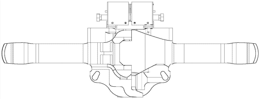
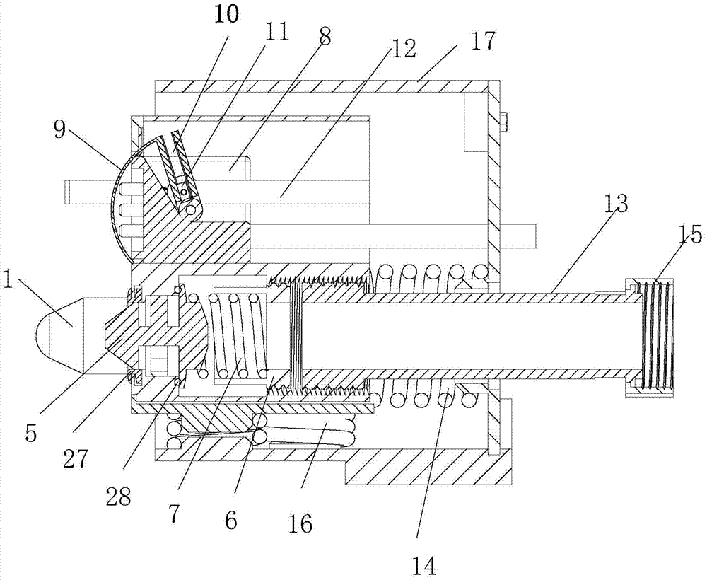
[0039] figure 2 It is a cross-sectional view of the automatic picking-and-hanging device for railway wagons in the detached state, including a fixing device 17 connected with the coupler, an air-way connecting device for connecting the ventilation pipe, and a circuit connecting device for connecting the circuit. Wherein, both the air duct connecting device and the circuit connecting device are installed in the fixing device 17, and the fixing device 17 is fixed on the coupler by bolts and moves together with the coupler. Preferably, the air duct connecting device is installed under the circuit connecting device.
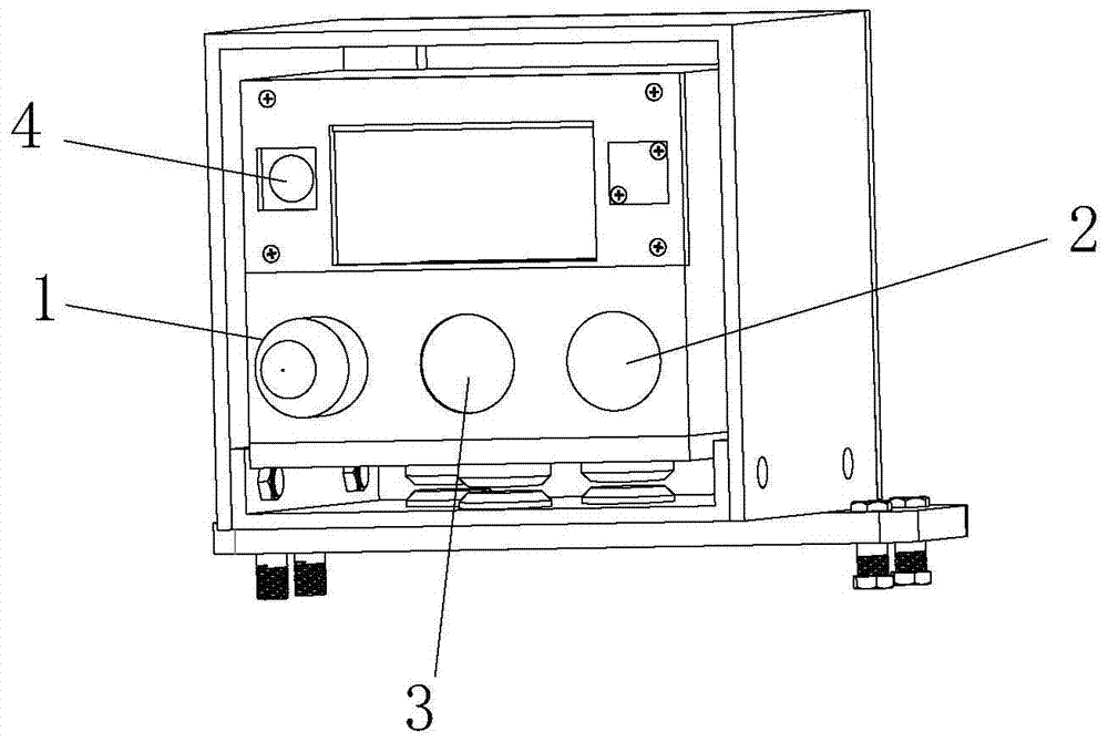
[0040] Wherein, the upper part of the fixing device 17 is provided with a rectangular groove for installing the circuit connection device, and the lower part is provided with the first through hole 3 communicating with the air duct. The structure of the fixing device is as follows: image 3 shown.
[0041] Wherein, the air path connection device includes a valve st...
Embodiment 2
[0066] like Figure 12As shown, the difference between the present embodiment and the first embodiment is that the inner surface of the sliding groove 10 in the present embodiment is provided with two rows of teeth 31, and the end of the U-shaped bar 12 close to the swing bar 30 is provided with a gear 32, and the gear 32 One side meshes with the tooth 31, and the other side of the tooth 31 leaves a certain gap, so that the tooth 31 can rotate in the sliding groove 10, and the gear 32 is connected to the U-shaped bar 12 in rotation.
[0067] When the coupler is connected, the U-shaped bar 12 overcomes the force of the return spring 18 and moves backward, driving the gear 32 to rotate backward, the swing lever 30 swings backward, and drives the safety cover 9 to swing backward to leak out of the electrical connection joint. The joints are butted with each other to connect the circuit; when the coupler is removed, the U-shaped bar 12 is moved forward by the force of the return s...
Embodiment 3
[0070] The difference between this embodiment and Embodiment 1 is that the driving device in this embodiment includes a micro switch installed on the fixing device 17, a controller, and a drive rod connected to the controller. The forward and backward movement of the driving rod is controlled, and the driving rod is slidably connected with the swing rod 30 .
[0071] When the coupler is connected, the automatic unhooking devices of railway freight cars on both sides are close to each other. When the contact is made, the micro switch is pressed by the external force of the fixing device, and an open control signal is sent to the controller. The controller controls the driving rod to move backward. Drive the swing rod 30 to swing backward, and at the same time, the safety cover 9 swings backward to leak out the electrical connection joint 8; when the coupler is removed, the automatic removal and hanging devices of the railway freight cars on both sides are far away from each othe...
PUM
 Abstract
Description
Claims
Application Information
 - R&D
- Intellectual Property
- Life Sciences
- Materials
- Tech Scout
- Unparalleled Data Quality
- Higher Quality Content
- 60% Fewer Hallucinations
Browse by: Latest US Patents, China's latest patents, Technical Efficacy Thesaurus, Application Domain, Technology Topic, Popular Technical Reports.
© 2025 PatSnap. All rights reserved.Legal|Privacy policy|Modern Slavery Act Transparency Statement|Sitemap|About US| Contact US: help@patsnap.com


