A Portable CT Loop Flow Tester

A portable, tester technology, applied in the field of testers, can solve problems such as inconvenience, wrong CT polarity, refusal to move, etc., and achieve the effect of easy portability and small size

Active Publication Date: 2018-02-02
STATE GRID CORP OF CHINA +1
View PDF7 Cites 0 Cited by
  • Summary
  • Abstract
  • Description
  • Claims
  • Application Information

AI Technical Summary

Problems solved by technology

It is extremely important to test the CT circuit: an open circuit of the CT circuit will generate high voltage, which may endanger the safety of personnel and equipment; wrong CT polarity, wrong connection of groups, and wrong phase of CT may cause protection malfunction, refusal to operate, or cause Electricity billing error
However, the existing test mode is extremely inconvenient: the relay protection tester used for through-current is large and heavy, and the weight of the power panel can reach 25-40 kg; the relay protection tester needs an external 220V AC power supply, especially outdoors The switch CT in the substation station that is far away from the power supply will need to be connected to more than two power panels, and a diesel generator will be used to supply power in case of a power outage in the whole station; when testing the main transformer bushing CT and 110KV switch CT, it is necessary to When working at heights, you will encounter the problem of insufficient length of the test line. It is necessary to use multi-strand test lines in series, which not only increases the man-hours, but if the exposed conductor part of the test line touches the ground shunt, the test will be inaccurate; and the flow test needs at least three people

Method used


Image

  • A Portable CT Loop Flow Tester
  • A Portable CT Loop Flow Tester

Examples


Embodiment Construction

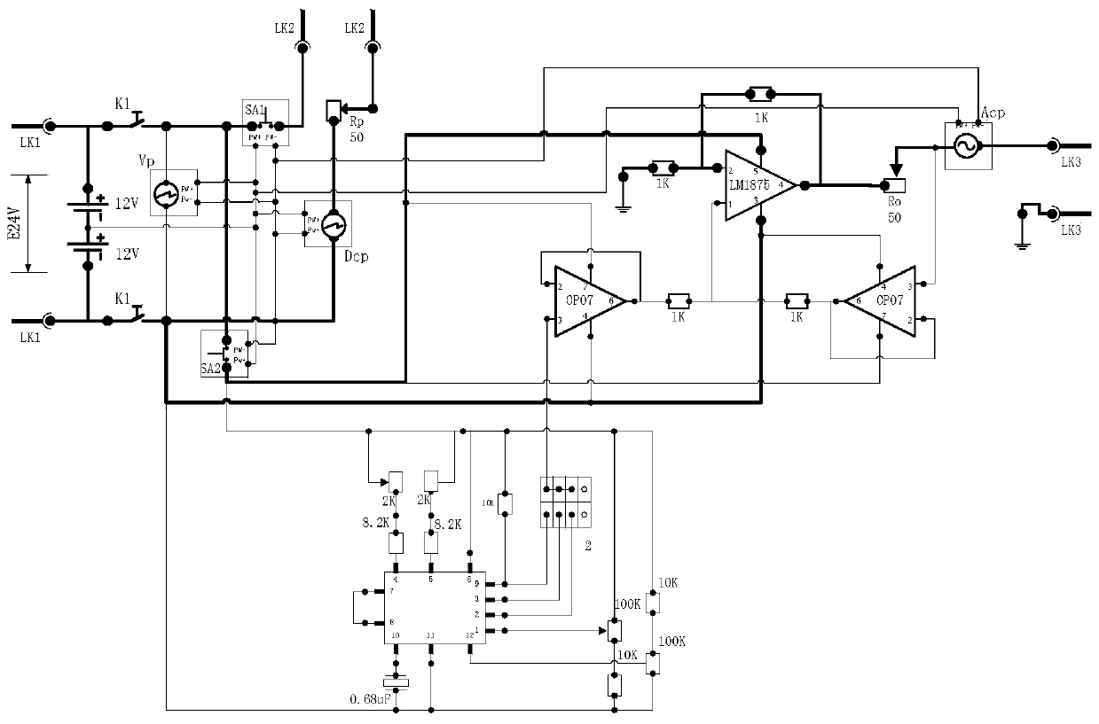
[0021] The present invention is described in further detail below in conjunction with accompanying drawing:

[0022] refer to figure 1 , the portable CT loop flow tester of the present invention comprises a casing, a circuit board and a battery for providing electric energy, the circuit board and the battery are all arranged in the casing; the circuit board is provided with a signal generator 1 , jumper 2, signal processing circuit and output terminal, the output end of the signal generator 1 is connected to one end of the jumper 2, the other end of the jumper 2 is connected to the input end of the signal processing circuit, and the output end of the signal processing circuit Connect to the output terminal.

[0023] It should be noted that the signal generator 1 includes a first resistor, a second resistor, a third resistor, a fourth resistor, a fifth resistor, a first adjustable resistor, a second adjustable resistor, a third adjustable resistor, a fourth Adjustable resisto...


PUM


Abstract

The invention discloses a portable CT loop current tester, which comprises a casing, a circuit board and a battery for providing electric energy, the circuit board and the battery are both arranged in the casing; the circuit board is provided with a signal generator , jumper, signal processing circuit and output terminal, the output end of the signal generator is connected to one end of the jumper wire, the other end of the jumper wire is connected to the input end of the signal processing circuit, and the output end of the signal processing circuit is connected to the output terminal connect. The volume of the invention is small, and the magnitude of the output current is controllable and stable.

Description

technical field [0001] The invention relates to a tester, in particular to a portable CT loop flow tester. Background technique [0002] As a component that converts a large primary current into a secondary small current, CT provides analog calculation references for relay protection, remote measurement and control, and meters, and is widely used in energy fields such as substations, switching stations, and power plants. Regardless of whether it is a new substation, a technical renovation of an old substation, or a new investment and calibration at intervals, CTs are required to be tested; each switch is equipped with multiple sets of CTs: 110KV switches generally have 12-15 sets of CTs; 10KV switches have 6 sets of CTs; in addition, the main transformer body There is also bushing CT, gap and zero sequence CT. A single-bus section 110KV substation is equipped with about 400 sets of CTs, and a double-bus 110KV substation is equipped with more than 600 sets of CTs. It is ext...

Claims


Application Information

Patent Timeline
Patent Type & Authority Patents(China)
IPC IPC(8): H03K3/02
Inventor 喻洋
Owner STATE GRID CORP OF CHINA
Why Eureka
Try Eureka