
Rolling potentiometer

A technology of potentiometer and ball, which is applied to the direction of the resistance element, resistance terminal/electrode, etc. adjusted by the auxiliary drive device, which can solve the problem of difficult positioning and achieve the effect of fast and accurate adjustment

Inactive Publication Date: 2015-11-04
CHENGDU ZHONGWEI ELECTRONICS MICROWAVE TECH
View PDF4 Cites 0 Cited by
  • Summary
  • Abstract
  • Description
  • Claims
  • Application Information

AI Technical Summary

Problems solved by technology

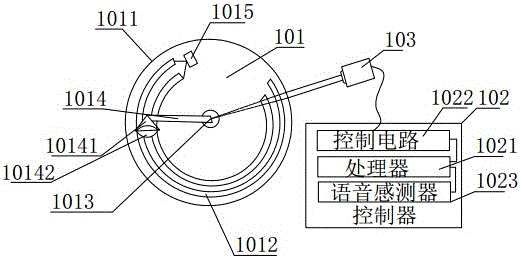
[0003] The embodiment of the present invention provides a rolling potentiometer, which solves the technical problem of difficult positioning in the prior art when adjusting the brush of the potentiometer, and further realizes the technical effect of being able to quickly and accurately adjust the potentiometer

Method used


Image

  • Rolling potentiometer

Examples


Embodiment Construction

[0011] The embodiment of the present invention provides a rolling potentiometer, which solves the technical problem of difficult positioning in the prior art when adjusting the brush of the potentiometer, and further realizes the technical effect of being able to quickly and accurately adjust the potentiometer.

[0012] In order to solve the existing technical problem of difficult positioning when adjusting the brush of the potentiometer, the technical solution of the present invention will be described in detail below in conjunction with the accompanying drawings and specific implementation methods.

[0013] A rolling potentiometer provided by an embodiment of the present invention, such as figure 1 As shown, it includes a potentiometer main body 101, a controller 102, and a motor 103. The potentiometer main body 101 includes an insulating bottom plate 1011, a rotating shaft 1013 arranged at the center of the insulating bottom plate 1011, and a semi-arc shape around the rotati...


PUM


Abstract

The invention relates to the technical field of an electronic component, and solves the technical problem of difficulty in adjustment positioning during adjusting a potentiometer brush in the prior art by providing a rolling potentiometer. The rolling potentiometer comprises a potentiometer body, a controller and an electric motor, wherein the potentiometer body comprises an insulation base plate, a rotary shaft, a semi-arc resistor body and a rolling brush, the rotary shaft is arranged at the center of the insulation base plate, the semi-arc resistor body is arranged on the insulation base plate, rotates around the rotary shaft and comprises at least two resistor bodies, the at least two resistor bodies are connected via a shift switch, the rolling brush comprises a conductive ball and a hopper-shaped support, the hopper-shaped support is used for embedding the conductive ball, the top end of the hopper-shaped support is fixedly connected with the rotary shaft, the ball is in tight contact with the semi-arc resistor body, the hopper-shaped support is made of conductive material, a controller comprises a processor, a control circuit and a voice sensor, the electric motor is connected with the rotary shaft, and the control circuit is connected with the electric motor. By the rolling potentiometer, the technical effect of rapidly and accurately adjusting the potentiometer can be further achieved.

Description

technical field [0001] The invention relates to the technical field of electronic components, in particular to a rolling potentiometer. Background technique [0002] In the prior art, when the potentiometer controls the output of the corresponding resistance value by adjusting the brush, multiple adjustments cause friction between the brush and the resistor body to cause damage to the potentiometer, and at the same time, the subsequent adjustment is not accurate enough. There are technical problems that are difficult to locate during the adjustment process. Contents of the invention [0003] The embodiment of the present invention provides a rolling potentiometer, which solves the technical problem of difficult positioning in the prior art when adjusting the brush of the potentiometer, and further realizes the technical effect of being able to quickly and accurately adjust the potentiometer. [0004] In order to solve the above technical problems, the present invention pr...

Claims


Application Information

Patent Timeline
Patent Type & Authority Applications(China)
IPC IPC(8): H01C10/14H01C1/14
Inventor 蒋孝林李翔
Owner CHENGDU ZHONGWEI ELECTRONICS MICROWAVE TECH
Learn More